Tuesday 21 December 2010

Zone Based Firewall & Port Forwarding

This article covers setting up port forwarding with Cisco Zone Based Firewall (ZBF) on a typical home connection.

There are a couple of steps:
1 - Give your LAN host a static IP.
2 - Set up NAT to handle the port forwarding
3 - Set up ZBF rules to allow the traffic


1 - Static IP


You can either manually configure the client or use a DHCP reserved address.

DHCP reservation is a royal pain on the Cisco 800 series, make sure there are no existing bindings when you try to configure it (show ip dhcp bindings), the basic configuration is:

ip dhcp pool MATT_PC
host 192.168.0.10 255.255.255.0
client-identifier 01aa.aabb.bbcc.cc
client-name Matt-PC


The client-identifier is the VLAN ID prepended to the MAC address. If that fails then you can try using "hardware-address aaaa.bbbb.cccc", strangely for my dual boot system Linux only picks up the reserved address using hardware-address config and Windows 7 only works using the client-identifier option. Use whatever works!


2 - NAT forwarding


You need several bits of information, the name of the external interface, the static IP used internally, the port and protocol (TCP/UDP) that you wish to forward. The format is:

ip nat inside source static <protocol> <LAN-IP> <port> interface <external-interface> <port>


e.g. a DSL router using Dialer0 interface to forward UDP traffic on port 88 to 192.168.0.10 is:
ip nat inside source static udp 88 192.168.0.10 interface dialer0 88


3 - Set up ZBF rules to allow the traffic


This is the actual Zone Based bit. You'll need to understand the setup to tweak it, no simple guides I'm afraid.

You need to know the name of your zones, I'm using the default setup which has called the outside/internet "out-zone" and internal/LAN "in-zone". It will show up in the interface configuration under the "zone-member security XXXX" option (e.g. found with "show run interface dialer0")

You basically make a policy, then apply that policy to traffic going between two zones.

You can use CBAC with the "inspect " command but in this case I'll use an access-list instead. ACL may be your only choice if the protocol you are forwarding is not one supported by CBAC. In this case it's Xbox-live or Games for Windows so one port may be kerberos (88) but the other is not known so an ACL is used. The steps are:


3a) Set up the ACL


I'm doing XBL so I need UDP/88, UDP/3074 and TCP/3074:
ip access-list extended GFW_Incoming
permit udp any host 192.168.0.10 eq 88
permit tcp any host 192.168.0.10 eq 3074
permit udp any host 192.168.0.10 eq 3074


3b) Set up a class-map to match the ACL


class-map type inspect match-any Incoming-Traffic
match access-group name GFW_Incoming


3c) Create a policy saying what to do to the traffic


policy-map type inspect incoming-policy
class type inspect Incoming-Traffic
pass
class class-default
drop

Note that "pass" means let it through. Inspect means run CBAC on it, but it must be a recognised protocol. "Drop" should be clear enough, you could include "drop log" but it will never log anything (see note * at end).


3d) Tell ZBF where the policy applies, specifically between which zones.


zone-pair security Outside-to-Inside source out-zone destination in-zone
service-policy type inspect incoming-policy


And that should be it!

To help troubleshoot, you can do show ip access-list GFW_Incoming and see if any packets are being matched.


Final note - why drop log doesn't log anything in this case.
ZBF creates a firewall policy for traffic going between two zones. In this case our policy is for traffic going between the out-zone (WAN) and the in-zone (LAN). The traffic is "routed" between those zones by the NAT rules doing the actual port forwarding.

Traffic that comes from the internet (out-zone) and hits the firewall without triggering a NAT rule is not going anywhere near the in-zone. The relevant policy would be out-zone to self-zone (the router itself).

So the only time our out-zone to in-zone policy can ever drop traffic is if the NAT rules are forwarding but our policy does not match (the ACL in this example), i.e. if it's configured wrong! If you want to log dropped traffic then you need to specify a policy for out-zone to self-zone and use logging on that.


Read more...

Thursday 27 May 2010

MST - Multiple Spanning Tree - Don't change the mappings!

MST allows you to create spanning-tree instances and map VLANs into them.

Combined with VTP version 3 means you can advertise the MST mappings automatically, as shown here.

MST has the concept of regions.

Whether a switch is a member of a particular region depends on three things:

  • The configured MST region name.

  • The configured MST revision number.

  • The VLAN to MSTI mappings.


The entire VLAN to MSTI mapping isn't advertised in each BPDU but a checksum of the mapping table is.

So why do I care?


Because if you change the mappings, you change the region.

If you change the region that the root bridge belongs to, it's a topology change and you trigger a total STP re-convergence.


So if you're in a live network and you tweak the VLAN-to-MSTI mappings then you'll cause a complete outage. If it's running VTPv3 then the outage will be longer as the change ripples through the network and switches "re-join" the region.

The solution


The solution in this case is fairly easy, set up all your mappings on day 1 and stick to them!

If you've two switches then you're best off finding a suitable way to distribute the VLANs, e.g.

MSTI 1 - VLANS 1 to 1999 - Root bridge SW1
MSTI 2 - VLANS 2000 to 4096 - Root bridge SW2

Then make sure you set up HSRP/VRRP in future to match where the MSTI is rooted for each particular VLAN.

Read more...

Wednesday 26 May 2010

Bundling Frame Relay Links

Frame-relay study time!

There are several ways to bundle links together in frame-relay:

  1. Frame-relay Multilink - FRF.16

  2. PPP Multilink


FRF16 requires configuration all along the path, so the service provider must support it. PPP multilink can be used on any frame-relay links and doesn't require anything from the SP.

Frame-relay Multilink - FRF.16


I'll be using the incredibly complicated topology shown below. To keep it simple the two routers are directly connected.


By default the "encapsulation frame-relay" command configures a device as a frame-relay DTE and two DTE's back-to-back won't talk. They'll both be sending LMI status enquiries but with no DCE to answer to tell them which DLCI is active, neither router will send any traffic. Using the "no keepalive" command brings the links up and stops the LMI messaging (which transmits every 6 keepalive cycles by default).


The configs are:


hostname R1
!
interface MFR1
ip address 192.168.0.1 255.255.255.0
no keepalive
frame-relay interface-dlci 100
!
interface Serial0/0
encapsulation frame-relay MFR1
clock rate 2000000
!
interface Serial0/1
encapsulation frame-relay MFR1
clock rate 2000000

hostname R2
!
interface MFR1
ip address 192.168.0.2 255.255.255.0
no keepalive
frame-relay interface-dlci 100
!
interface Serial0/0
encapsulation frame-relay MFR1
!
interface Serial0/1
encapsulation frame-relay MFR1


You can check the multilink status as below:

R1#show frame-relay multilink
Bundle: MFR1, State = up, class = A, fragmentation disabled
BID = MFR1
Bundle links:
Serial0/1, HW state = up, link state = Up, LID = Serial0/1
Serial0/0, HW state = up, link state = Up, LID = Serial0/0


PPP Multilink


In this case I've added a frame-relay switch in the middle.


It's providing two separate VCs and they are being bundled together at either end using PPP multilink. Configs are below:


hostname R1
!
interface Serial0/0
encapsulation frame-relay
frame-relay interface-dlci 102 ppp Virtual-Template1
!
interface Serial0/1
encapsulation frame-relay
frame-relay interface-dlci 304 ppp Virtual-Template1
!
interface Virtual-Template1
ip address 192.168.0.1 255.255.255.0
ppp multilink


hostname R2
!
interface Serial0/0
encapsulation frame-relay
frame-relay interface-dlci 201 ppp Virtual-Template1
!
interface Serial0/1
encapsulation frame-relay
frame-relay interface-dlci 403 ppp Virtual-Template1
!
interface Virtual-Template1
ip address 192.168.0.2 255.255.255.0
ppp multilink


Don't need to disable the keepalives now as there's a FR switch responding to LMI status queries.

To test the bundle, use "show ppp multilink". The Virtual-Access interfaces are randomly generated by PPP from the virtual-template and may not always be the same.

R1#show ppp multilink

Virtual-Access4, bundle name is R2
Endpoint discriminator is R2
Bundle up for 00:05:50, total bandwidth 200000, load 1/255
Receive buffer limit 24384 bytes, frag timeout 1000 ms
0/0 fragments/bytes in reassembly list
0 lost fragments, 0 reordered
0/0 discarded fragments/bytes, 0 lost received
0x2 received sequence, 0x2 sent sequence
Member links: 2 (max not set, min not set)
Vi1, since 00:05:50
Vi2, since 00:05:50
No inactive multilink interfaces

R1#show int vi1
Virtual-Access1 is up, line protocol is up
Hardware is Virtual Access interface
Internet address is 192.168.0.1/24
MTU 1500 bytes, BW 100000 Kbit, DLY 100000 usec,
reliability 255/255, txload 1/255, rxload 1/255
Encapsulation PPP, LCP Open, multilink Open
Link is a member of Multilink bundle Virtual-Access4
PPPoFR vaccess, cloned from Virtual-Template1
Vaccess status 0x44
Bound to Serial0/0 DLCI 102, Cloned from Virtual-Template1, loopback not set

R1#show int vi2
Virtual-Access2 is up, line protocol is up
Hardware is Virtual Access interface
Internet address is 192.168.0.1/24
MTU 1500 bytes, BW 100000 Kbit, DLY 100000 usec,
reliability 255/255, txload 1/255, rxload 1/255
Encapsulation PPP, LCP Open, multilink Open
Link is a member of Multilink bundle Virtual-Access4
PPPoFR vaccess, cloned from Virtual-Template1
Vaccess status 0x44
Bound to Serial0/1 DLCI 304, Cloned from Virtual-Template1, loopback not set


Read more...

Monday 24 May 2010

SNMP Trap on VSS Failover

One of the big things that Cisco VSS is missing is the ability to clearly see when it's failed over.

You set up your spanking new 6500 with 10Gig supervisors, plug it into your network management, lose one of the boxes and get a few traps about routing problems. What you really want is a big in-your-face message saying "HELP ME THE VSS JUST FAILED OVER OH MY GOD THE SKY IS FALLING!!11!one" and it's not there. It'd be fairly easy to miss that anything happened at all.

One fix is to use the Embedded Event Manager (EEM) and hook it on one of the syslog messages. There's no obvious "WAAAH HELP VSS JUST DIED" message in syslog either, but it does have a few that pop up on failover such as this one (which also occurs on first VSS bootup but I'm not too fussed about an extra trap in that case):

%PFREDUN-SW2_SPSTBY-6-ACTIVE: Initializing as Virtual Switch ACTIVE processor


EEM lets you create an action that runs when this message appears in the log, I'll make it send an SNMP trap and write a clearer syslog. The following code is beerware, feel free to re-use and re-distribute. I'd appreciate a beer if you meet me (or at least link this site):

event manager applet VSS_active_state_change
event syslog pattern ".*%PFREDUN-.*_SPSTBY-6-ACTIVE.*"
action 1.0 snmp-trap strdata "VSS Failover - New Active VSS Supervisor"
action 1.1 syslog priority alerts msg "VSS Failover - New Active VSS Supervisor"


Now you get an SNMP trap and a SYSLOG saying:

*May 24 19:49:36.267: %HA_EM-1-LOG: VSS_active_state_change: VSS Failover - New Active VSS Supervisor


You can change the %HA_EM to something else with the "facility XXX" option in the syslog line, but it doesn't seem to be present on the 6500 with SXI3 IOS.

This does need EEM traps enabled, or you still won't have any alerts:
snmp-server enable traps event-manager


Read more...

Monday 22 March 2010

Basic PPPoE Lab

Configurations below for a PPPoE lab, directly connecting two routers. This uses the new broad-band access (bba) command instead of the old VPDN ones.


Client:
interface Dialer1
ip address 192.168.0.10 255.255.255.0
encapsulation ppp
dialer pool 1

interface FastEthernet0/0
pppoe-client dial-pool-number 1


Server:
interface Virtual-Template1
ip address 192.168.0.1 255.255.255.0

bba-group pppoe global
virtual-template 1

interface FastEthernet0/0
pppoe enable


Or to use DHCP, the client would be:
interface Dialer1
ip address dhcp
encapsulation ppp
dialer pool 1

interface FastEthernet0/0
pppoe-client dial-pool-number 1


And server config:
ip dhcp excluded-address 192.168.0.1

ip dhcp pool IP_POOL
network 192.168.0.0 255.255.255.0

interface Virtual-Template1
ip address 192.168.0.1 255.255.255.0
peer default ip address dhcp-pool IP_POOL

bba-group pppoe global
virtual-template 1

interface FastEthernet0/0
pppoe enable


Read more...

Thursday 18 March 2010

Generate Strong Passwords from a Unix Box

Works from any form of unix that has a /dev/urandom and has uuencode installed.


head -n 2 /dev/urandom | uuencode -m -


Read more...

Saturday 20 February 2010

IBM Blade Centers - CIGESM Configuration

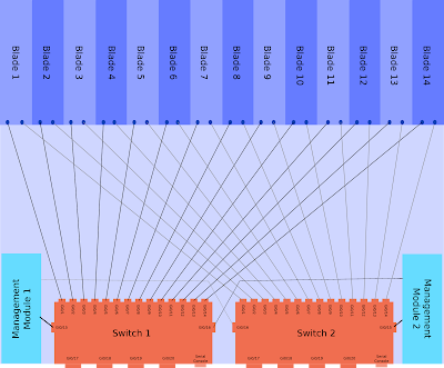
There are lots of docs from IBM explaining the blade center architecture but it's a lot of information to filter through if you're only interested in the network side.

The blade center in this example holds 14 blades which are best thought of as individual physical servers. It can use the Cisco switching module called a Cisco Systems Intelligent Gigabit Ethernet Switch Module, or CIGESM. They do run IOS but they don't behave in quite the same as normal Cisco switches.

Architecture


The CIGESM is a Cisco switch with 20 Gigabit Ethernet ports, these are:

  • 4 Physical ports on the back of the chassis.

  • 14 Ports connecting to the individual blades.

  • 2 Ports connecting to the internal Management Module for managing the switch via the chassis web interface.


Each of the blades is dual homed into the two CIGESM modules.

This architecture of a single blade center is shown below, click for larger version (warning 400kb image). This one assumes two management modules and two CIGESMs.


Management


The blade center itself is configured via a web interface that runs on the management module (MM). To access this initially you connect a copper cable directly into the MM port (has a picture of a network next to it), give your laptop an address in the 192.168.70.0/25 range and browse to 192.168.70.126. The default login is USERID/PASSW0RD (zero).

The CIGESM is a layer 2 switch and has a defined management interface, with the command "management" under the SVI. The Blade Center Management Module (MM) will configure the IP address on this interface. You can change it on the Cisco CLI but it will probably get set back by the MM at some point in future, so set it to the same on both MM and CLI!

CIGESM Management SVI


If you want to change the management interface VLAN then you'll need to do the following:

  1. If the IP is changing then update the network settings via the blade center web interface first.

  2. Create the layer 2 VLAN (for applying config to ports 15/16).

  3. Create the layer 3 SVI.

  4. Run the command "management" under the layer 3 SVI.

  5. Delete the old management interface.


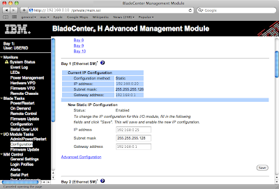
The web interface screen is shown below (names changed to protect the innocent), the network settings are under "I/O Module Tasks" -> "Configuration". Click for larger image:


An example of changing the management VLAN from 1 to 2, note the auto updates to Gi0/15&16 (explained later):

BC-Sw01(config-if)#int vlan 2
BC-Sw01(config-if)#management
Port Gi0/15 allowed vlan list updated to include vlan 2
Port Gi0/16 allowed vlan list updated to include vlan 2

BC-Sw01(config-if)#desc Management Interface
BC-Sw01(config-if)#ip address 192.168.0.25 255.255.255.128
BC-Sw01(config-if)#do show run interface vlan 2
interface Vlan2
description Management Interface
ip address 192.168.0.25 255.255.255.128
no ip route-cache
management
end


Internal Connections - Gi0/15 & Gi0/16


As shown in the architecture diagram above ports 15 & 16 are internal links to the management modules. These are used for communications between the MM and the switch, for instance if you click the "telnet" link within the MM web interface.

The management VLAN needs to be allowed over the internal link to the MM. Some parts of the configurations on these ports cannot be configured manually, such as access or native VLAN. These entries are set automatically when you specify an SVI for management.

If you try to reconfigure them on the CLI you'll see errors as below:
BC-Sw01(config)#int range gi0/15 - 16
BC-Sw01(config-if-range)#switchport access vlan 2
User prevented from modifing Ethernet port Gi0/15 access vlan

Command rejected: not allowed on this interface.User prevented from modifing Ethernet port Gi0/16 access vlan

Command rejected: not allowed on this interface.
BC-Sw01(config-if-range)#switchport trunk native vlan 2
User prevented from modifying Native VLAN on Port Gi0/15

Command rejected: not allowed on this interface.User prevented from modifying Native VLAN on Port Gi0/16

Command rejected: not allowed on this interface.
BC-Sw01(config-if-range)#switchport trunk allowed vlan 2
BC-Sw01(config-if-range)#


Read more...

Wednesday 17 February 2010

Creating a CRL for an OSX keychain CA

OSX has a handy keychain utility that can be used to create a CA among other things. I needed a CRL generated for my keychain-created CA in order to use certificate-based VPNs on a Netscreen box.


There are probably 101 ways of doing this, mine is:

Make a CA structure as per /opt/local/etc/openssl/openssl.cnf
(or alternately you could provide the suitable CLI options to openssl each time)


mkdir -p demoCA/private
echo 01 > demoCA/serial
echo 01 > demoCA/crlnumber


Locate your CA private key in the keychain utility, right click and export. This saves it as pkcs12 format.

Convert it to PEM format with:
openssl pkcs12 -nocerts -in My_Macbook_CA.p12 -out demoCA/private/cakey.pem


Edit it and delete the text above:
-----BEGIN RSA PRIVATE KEY-----


(this last step probably isn't necessary)

Export the CA certificate from keychain and change the format to PEM.

Then you can generate the CRL with:
openssl ca -gencrl -out crl.pem -cert exported_cert.pem


If you get any errors then check the paths, the default openssl config puts this in ./demoCA

Note that this creates a CRL valid for 30 days only with the default openssl.cnf, you probably want to increase this by editing /opt/local/etc/openssl/openssl.cnf and changing the default_crl_days value.


Read more...

Friday 12 February 2010

ToS DSCP Mappings

Reference table of ToS to DSCP mappings below.


PHB Value ToS Byte String DSCP Value
CS0 0 Routine 0
CS1 32 PRIORITY 8
AF11 40 10
AF12 48 12
AF13 56 14
CS2 64 IMMEDIATE 16
AF21 72 18
AF22 80 20
AF23 88 22
CS3 96 FLASH 24
AF31 104 26
AF32 112 28
AF33 120 30
CS4 128 FLASHOVERRIDE 32
AF41 136 34
AF42 144 36
AF43 152 38
CS5 160 CRITICAL 40
EF 184 46
CS6 192 INTERNETWORK CONTROL 48
CS7 224 NETWORK CONTROL 56


Read more...

Tuesday 9 February 2010

VTP Version 3 and MSTP Walkthrough.

This article assumes you are familiar with MSTP and VTP.

The latest incarnation of VTP version 3 is now available on versions of IOS from 12.2(50)SE3 onwards for 3560, 3750 and 2960s.

It supports distribution of two databases:

  • VLAN Database.

  • MSTP Vlan-to-MSTI mapping database.


Other than support for extended ID VLANs the VLAN database functionality is the same as previous versions. The MST mappings were not previously supported however and you had to manually create them on every device before. They show which VLANs are part of which spanning tree (or MSTI).

Another VTP version 3 function is to define a primary server that will not accept updates from any other device. This is meant to stop VTP bombs. When a switch is configured as the primary server it broadcasts itself on the network, the other VTP devices then create an entry with the MAC of this primary server and refuse to accept updates from any other device.

Implementation


The outputs here are from a sup720 running SXI3 IOS.

Previously you only had to set the VTP server, version and spanning-tree mode globally with commands such as:

RTR01(config)#vtp mode server
RTR01(config)#vtp version 3
RTR01(config)#spanning-tree mode mst


This configures the VTP status as follows, VTP server but leaves VTP support for MSTP in transparent mode.

RTR01#sh vtp status
VTP Version : 3 (capable)
VTP version running : 3
VTP Domain Name : VTPDOMAIN
VTP Pruning Mode : Disabled (Operationally Disabled)
VTP Traps Generation : Enabled
Device ID : 0200.0000.000a

Feature VLAN:
--------------
VTP Operating Mode : Server
Number of existing VLANs : 5
Number of existing extended VLANs : 0
Configuration Revision : 0
Primary ID : 0000.0000.0000
Primary Description :
MD5 digest : 0x00 0x00 0x00 0x00 0x00 0x00 0x00 0x00
0x00 0x00 0x00 0x00 0x00 0x00 0x00 0x00


Feature MST:
--------------
VTP Operating Mode : Transparent


To set the server as the primary use the command “vtp primary vlan”, in enable mode not config mode.

RTR01#vtp primary vlan
This system is becoming primary server for feature vlan
No conflicting VTP3 devices found.
Do you want to continue? [confirm]

This then shows the log message:

000087: Feb 8 14:12:55.145: %SW_VLAN-SW1_SP-4-VTP_PRIMARY_SERVER_CHG: 0200.0000.000a has become the primary server for the VLAN VTP feature


At this point only the configured primary server can send VTP updates to the networks. Clients should ignore updates from any other device. The VTP status is now updated to show the VTP primary server.

RTR01#sh vtp status
[snip]

Feature VLAN:
--------------
VTP Operating Mode : Primary Server
Number of existing VLANs : 5
Number of existing extended VLANs : 0
Configuration Revision : 1
Primary ID : 0200.0000.000a
Primary Description : RTR01
MD5 digest : 0x87 0xBB 0xDB 0xEC 0xE5 0x9F 0x9C 0xCA
0x75 0xCE 0x4A 0x67 0xA7 0x67 0xBF 0xDA


The VLAN database is being synced but the MST mappings are not. To set up the device as the primary server for MST requires a few more steps:

RTR01(config)#vtp mode server mst
Setting device to VTP Server mode for MST.
RTR01(config)#^Z
RTR01#vtp primary mst
This system is becoming primary server for feature mst
No conflicting VTP3 devices found.
Do you want to continue? [confirm]
000091: Feb 8 14:15:20.932: %SW_VLAN-SW1_SP-4-VTP_PRIMARY_SERVER_CHG: 0200.0000.000a has become the primary server for the MST VTP feature


Now the VTP status is updated to show the primary server for both VLAN and MST.

RTR01#show vtp status
VTP Version : 3 (capable)
VTP version running : 3
VTP Domain Name : VTPDOMAIN
VTP Pruning Mode : Disabled (Operationally Disabled)
VTP Traps Generation : Enabled
Device ID : 0200.0000.000a

Feature VLAN:
--------------
VTP Operating Mode : Primary Server
Number of existing VLANs : 5
Number of existing extended VLANs : 0
Configuration Revision : 1
Primary ID : 0200.0000.000a
Primary Description : RTR01
MD5 digest : 0x87 0xBB 0xDB 0xEC 0xE5 0x9F 0x9C 0xCA
0x75 0xCE 0x4A 0x67 0xA7 0x67 0xBF 0xDA


Feature MST:
--------------
VTP Operating Mode : Primary Server
Configuration Revision : 1
Primary ID : 0200.0000.000a
Primary Description : RTR01
MD5 digest : 0xC6 0x62 0xA6 0x96 0x7E 0x98 0x14 0xCB
0x80 0xA1 0xA6 0x2D 0x60 0x39 0x49 0x39


Any devices on the network running VTP version 3 in the correct VTP domain should now sync VLANs and MST mappings.

EDIT:
Should really include the client configuration as that has also changed slightly, the old way was:

vtp domain XXXX
vtp mode client


To get the MST mappings you also need to run the command:

vtp mode client mst


And because changing the MST mapping later causes a total STP reconvergence you should configure all the MST mappings on day 1, but more about that later :-)


Read more...

Saturday 6 February 2010

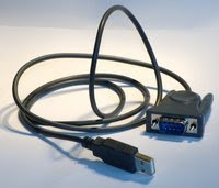
How to get USB serial adapters working in OSX

There are loads of cheap USB serial adapters around, the difficulty can be working out what chipset they use.

The easiest way to identify them is with a Linux live-CD.


Identify the chipset in Linux


You could just install the two drivers linked below, it won't do any harm if they're the wrong ones and there probably aren't that many different USB serial chipsets around so there's a good chance it'll work.

To make sure you'll need to identify the hardware using a Linux live CD. Ubuntu will do the job, also Knoppix. Pretty much any distribution should include a kernel with most of the drivers these days.

Boot up the live CD and plug in the USB serial adapter, load a terminal and run "dmesg" to see the system log. It should show the chipset that was detected and from there it's a simple google query to find the OSX driver.

Example output for this prolific one, drivers available from the manufacturor for OSX.
[ 6786.920018] usb 2-1: new full speed USB device using ohci_hcd and address 5
[ 6787.146546] usb 2-1: configuration #1 chosen from 1 choice
[ 6787.204328] usbcore: registered new interface driver usbserial
[ 6787.204346] USB Serial support registered for generic
[ 6787.204414] usbcore: registered new interface driver usbserial_generic
[ 6787.204417] usbserial: USB Serial Driver core
[ 6787.211673] USB Serial support registered for pl2303
[ 6787.211740] pl2303 2-1:1.0: pl2303 converter detected
[ 6787.243536] usb 2-1: pl2303 converter now attached to ttyUSB0
[ 6787.243559] usbcore: registered new interface driver pl2303
[ 6787.243562] pl2303: Prolific PL2303 USB to serial adaptor driver


This one is from FTDI who also have drivers for OSX.

[ 6922.152793] USB Serial support registered for FTDI USB Serial Device
[ 6922.152913] ftdi_sio 2-1:1.0: FTDI USB Serial Device converter detected
[ 6922.152944] usb 2-1: Detected FT232BM
[ 6922.152947] usb 2-1: Number of endpoints 2
[ 6922.152949] usb 2-1: Endpoint 1 MaxPacketSize 64
[ 6922.152952] usb 2-1: Endpoint 2 MaxPacketSize 64
[ 6922.152955] usb 2-1: Setting MaxPacketSize 64
[ 6922.154724] usb 2-1: FTDI USB Serial Device converter now attached to ttyUSB0
[ 6922.154752] usbcore: registered new interface driver ftdi_sio
[ 6922.154755] ftdi_sio: v1.5.0:USB FTDI Serial Converters Driver


Install the OSX Driver


Install the driver in OSX and connect the serial adapter, run "sudo dmesg" in a terminal and you should see the driver being loaded:
FTDIUSBSerialDriver:        0  4036001 start - ok


The serial port is presented as a character device entry in /dev/. You can read and write from this like any other character device with normal terminal commands, e.g.
echo "show run" > /dev/tty.USBSERIAL && cat /dev/tty.USBSERIAL


The serial drivers in OSX aren't consistent, some name the device as /dev/tty.USBSERIAL, but not all. The only devices that start with the string "tty." are the Bluetooth serial emulation ones (which all have Bluetooth in the filename) and the USB serial so it's easy to find them with
Matts-Macbook:~ matt$ ls /dev/tty.*
/dev/tty.Bluetooth-Modem
/dev/tty.Bluetooth-PDA-Sync
/dev/tty.usbserial-FTCC130A


Terminal Software


Then all you need is terminal software. You can try putty from macports but it won't talk to my serial ports. Screen is included in OSX and can be used to talk to the serial:
screen /dev/tty.USBSERIAL

There's also Zterm & macwise.

My preferred option is to install minicom from macports. It's not as pretty but it has the features I need:

  • It supports Xmodem, Zmodem and a whole host of other transfer protocols.

  • It can log the entire session.

  • It's free.

  • It has menus so you don't have to remember three million keyboard shortcuts.

  • It works.


What more do you need!


Read more...

Friday 5 February 2010

Cisco Gotchas - 1800 Virtual Ports

This is a (very late) addition to the article here.

Cisco 6500 doesn't directly limit the number of spanning-tree instances. It has limits on the number of virtual ports per line card.


A virtual port is a VLAN being forwarded on a trunk. So if you have 10 VLANs and 5 active trunks with no pruning then you have 50 virtual ports.

A 6500 is limited to 1800 virtual ports per line-card (with caveats, see below!).

If you have a full 48-port linecard and use PVST then you can only create 37 VLANs before you hit the limit. If you intend to go over this then either manually prune some VLANs or upgrade.

Some of the SX IOS versions have removed the virtual port limit on the newer linecards (6500 and 6700 series), however the per-chassis limits still apply.

The per-chassis limits are shown here.

They are 10000 for RPVST+ and 13000 for PVST+, updated in IOS 12.2(33)SXI to be 12000/15000 respectively.


If you want to get extra lifetime out of older linecards then look into using MST as it drastically simplifies the forwarding. Unless you have a need for a different STP topology for every VLAN then it's a great idea.


Read more...

Cisco Gotchas - Max VLANs and STP Instances

Cisco switches have separate limitations on:

  • The number of VLANs that can exist in the database.

  • The number of Spanning-Tree Instances that can run.


Cisco kit tends to use per-VLAN spanning-tree in which case the two values will be the same.


To understand the problem and solution requires knowledge of the different types of spanning-tree available, this subject is huge but very briefly the types are:

  1. Standard 802.1D Spanning-Tree

  2. PVST, Per-VLAN Spanning-Tree (ISL trunking only)

  3. PVST+, Per-VLAN Spanning-Tree plus (compatible with 802.1q trunks)

  4. Rapid PVST - RSTP version of PVST+

  5. MST - Multiple Spanning Tree


The limitations are as follows on switches running PVST, PVST+ or Rapid-PVST:

  • 2950 SI: Maximum 64 STP instances, Maximum 128 VLANs.

  • 2950 EI: Maximum 64 STP instances, Maximum 250 VLANS.

  • 3550, 3560, 3750: Maximum 128 STP instances, Maximum 1005 VLANs.

  • 6500: Based on logical ports. Article here.


If you exceed the number of VLANs then you'll get an error like this:
SPANTREE_VLAN_SW-2-MAX_INSTANCE: Platform limit of 64 STP instances exceeded. No instance created for VLANxxx


Solutions


There are a couple of workarounds:

  • Delete some VLANs!

  • Manually prune VLANs off the trunk links and set the switch to VTP mode transparent so it doesn't know about the extra VLANs.

  • Use MST instead of PVST.


MST is my preferred option. Most networks will only require 2 or 4 Spanning-Tree topologies anyway so it is wasteful to have STP running in every VLAN.


Read more...

Cisco Gotchas - 16 Unique Standby Groups

HSRP is configured in standby groups, each one having an identifier value in the switch configuration.

The acceptable range of values is 0-255 and you can create as many as you want. Cisco don't recommended using more than 500 on a 6500 series or 64 on the 3550.

There are limitations on the number of unique ID values you can assign however.


Each instance is configured using the standby command:

interface FastEthernet 0/10
ip address 10.0.0.3 255.255.255.0
standby 10 ip 10.0.0.1
standby 10 preempt


The gotcha is that you can create as many groups as you want, but you can only use 16 different values for the ID.

This is hardware/software specific, but it's not clear what hardware it's specific to. The Cisco FAQ says it only affects PFC2, but their bug tracker doesn't mention the PFC and has a "fixed in" entry indicating that it's not an issue with newer software.

So feel free to create as many unique IDs as you like, but when adding the 17th check the logs to make sure it's actually working!

Or you could use VSS and get rid of HSRP entirely.

The Cisco FAQ for this issue on the 6500 is here.
There is a bug open on the Cisco tracker, CSCdx32496.


Read more...

Monday 1 February 2010

Configure IOS by SNMP - Password Recovery

This is useful if you ever end up without a password for a router but you do know the SNMP read-write community values or usernames. It can save you the need to reboot a device and do a full password recovery, useful if the device is a thousand miles away and running some vital service.

You can load a configuration snippet into IOS from a TFTP server, triggered over SNMP.

The steps are:


Warning:

This can seriously b0rk your equipment and I accept no responsibility if it doesn't work for you. If your device is thousands of miles away, running critical services and you cannot login then your network has bigger issues than bodging the username on this one device! Don't do this unless you understand the possible consequences of blindly applying raw config to a Cisco device.


  1. Create a text file containing the config snippet.

  2. Run a TFTP server, on machine with IP 10.0.0.10 in this example.

  3. Set the value of iso.org.dod.internet.private.enterprises.cisco.lo cal.lsystem.hostConfigSet.10.0.0.10 to a string containing the filename from #2


The config snippet could be something like:

username cisco priv 15 password cisco


The command line for NET-SNMP tools snmpset is:

snmpset <router> <community> .iso.org.dod.internet.private.enterprises.cisco.local.lsystem.hostConfigSet.10.0.0.10 s <filename>


You can do a write mem via SNMP too if you want (but I wouldn't recommend it):

snmpset <router> <community> .iso.org.dod.internet.private.enterprises.cisco.local.lsystem.writeMem.0 i 1


If you can't login to a device and have absolutely no idea why not then it may not be as simple as adding a new local account. The specifics may be guessed at depending on how standardized your network is and you may be able to guess at the extra bits (heed the warning above), e.g.

no aaa new-model
username cisco priv 15 password cisco
line vty 0 15
login local
password cisco


Read more...

Saturday 16 January 2010

VSS Introduction

VSS stands for Virtual Switching System and is a technology for use on 6500 series switches.

It works in a similar way to stackwise on the 3750s, you have two physical devices that end up with a single logical management plane.


In a large Cisco-style network you would have two core/distribution devices for redundancy. The network topology will typically need an active/standby topology. With Spanning-tree, only one uplink is forwarding for a given VLAN. To avoid unicast flooding the network should then have HSRP/VRRP and the IGP configured so that all traffic for that VLAN is routed via the same distribution (or core) switch.

Traffic is load balanced by alternating VLANs between the two distribution switches.

This topology is shown below for a single VLAN:


The basic VSS topology is shown below, the access device still has redundant uplinks but traffic flows over all links in etherchannels:


This topology it produces is similar to a network built around Nortel kit and the Split Multi-Link Trunking (SMLT) technology. The difference being that SMLT still has two separate management planes but VSS only has one.

There are a few benefits to this system:

Simplified Network Architecture.
  • Single logical device at the core/distribution layer.
  • Behaves as a single unit for management purposes.
  • No need to fudge STP, HSRP and IGP per VLAN.
  • No need of first hop redundancy protocols (FHRP).

Simpler Routing
  • Half as many IGP neighbors.
  • Half as many IGP routes.
  • No IGP load balancing/weighting required.


ISSU.
  • Software upgrades carried out without risky failovers and associated downtimes during convergence.
  • Easier to roll back.

Faster Convergence.
  • No STP convergence delays.
  • Loss of redundant switch does not change logical topology, avoiding convergence entirely.

Reduced function of Spanning-Tree.
  • No blocked ports to distribution/core from access layer.
  • Reduces greatly the chance of bridging loops.
  • Can use portfast trunk on access device uplinks.


The Cisco VSS Design Guide is well worth a read for more detailed information.


Read more...

3750 Stackwise Upgrades

Upgrading a Cisco switch is very easy:
  1. Copy IOS image to the flash drive on the switch.
  2. Point the boot statement at the new image.
  3. Reboot the switch.
The 3750 stack is made up of several physical devices with just a single logical management interface so Cisco has implemented the archive-sw command to make upgrading it easy. It doesn't quite work as well as it should and I wouldn't recommend using it. The method below is much easier and more reliable:

1. Copy IOS image to the flash drive on the switch
Use the same command as usual, but run it once for each switch in the stack. The flash drives are numbered flash1: flash2: flash3: etc.
copy tftp flash1:
copy tftp flash2:

Delete any old images or html files to clear space as necessary.

2. Point the boot statement at the new image
This can be done with a one liner (replace image.bin with whatever file you want to use):
boot system all flash:image.bin


3. Reboot the switch
The "reload" command will restart the entire stack.

So what's wrong with archive-sw?
The upgrade process is just the 3 simple steps above. Last time I used archive-sw I had about 45 minutes of instability while various individual processes restarted on the switch, routing went down but basic IP services stayed up so HSRP couldn't fail over and the network was unreachable until archive-sw had finished doing whatever it was doing. Maybe it was a bug in the archive-sw version I was using, maybe the config on that device triggered it, maybe it's just not very good.

Either way, I'm sticking to the old method of upgrades because it works and only causes an outage for the time it takes the switch to reboot (assuming it comes up again, which doesn't always happen with stacks!).


ISSU - In Service Software Upgrades
ISSU allows devices to be upgraded without outage. Unfortunately it is not available for 3750 stacks.
It may be possible to carry out the instructions above and then just reboot one switch at a time in the stack, if the old and new versions are similar enough then you might get away with it and the stack might re-form, allowing you to reboot the other switch while maintaining connectivity. Personally I wouldn't try it, if you want maximum uptime then you need two separate logical switches or to forget about upgrading them.


This method was worked out with our partners are Cacti Networks Ltd, network and security providers in the Ross-on-Wye area.

Read more...

Monday 11 January 2010

Rapid Spanning Tree Notes

Just been reading a bit on RSTP, there are plenty of excellent detailed resources around. Here's my summary.


PDF version available here


Rapid Spanning Tree - 802.1w
Port Roles

Role

Description

Detailed

Root

Path to root bridge

The port that is closest to the root bridge in terms of path cost.

Designated

Forwarding to a segment

The port that sends the best BPDU on the segment to which it is connected.

Alternate

Alternative path to root

Alternate route to the root bridge. This port receives more useful BPDUs from another bridge. State blocked. Can be activated if the root port fails (RSTP equivalent to uplinkfast).

Backup

Redundant port

This port receives more useful BPDUs from the local bridge, therefore is redundant. State is blocked.

Disabled

Shutdown

Administratively shut down.


Port States

State

Description

Discarding

Combines the 802.1D disabled, blocking and listening states.

Learning

Drops frames but learns MAC addresses.

Forwarding

Sends frames


Port Types

Type

Description

Edge

End host, selected when portfast is enabled.

Root

Path to root bridge.

Point-to-point

Designated port to another switch. Selected when non-edge port is in full duplex mode.


  • It is assumed that a non-edge port in half-duplex mode may connect to a shared medium with multiple peer switches. These ports will fall back to 802.1D compatibility mode.

  • A non-edge port transitioning to forwarding will generate a TCN.


BPDUs

  • All switches send BPDUs out of all ports.

  • Loss of 3 BPDUs from a neighbour is taken to mean the neighbour is down. All information on that port is aged out.

  • If an 802.1D BPDU is received then that port falls back to 802.1D mode from RSTP.


Read more...

Sunday 3 January 2010

DSL Firewalls and PPP Half Bridges

A PPP Half Bridge lets you extend the public IP address of your network into the LAN. This is useful if you have a firewall that doesn't have it's own DSL modem and want to do VPNs.

It's also known as DHCP spoofing.


Half bridging is a hack where your DSL modem makes the PPPoA connection to your ISP and is issued a public address, then advertises that same IP back on the LAN with a very short DHCP lease time. It then goes into bridging mode and forwards all traffic to the LAN host. The LAN host is effectively directly connected to the internet.

This is useful if you want to avoid NAT for any reason, e.g. to terminate VPNs.

The topology is shown below:


There's a big cost benefit to connect a firewall device to the DSL connection without requiring a built-in DSL modem.

Cisco's firewall line is the ASA which has no DSL module available so the only option is to use an external ADSL router. The low-end box is the 5505 which can be picked up from around £250 depending what software license you want.
They also have the 857W (~£300) and 877W for around £400 which include both wireless, VPN capability and DSL ports. However these are routers, not firewalls. They may be able to run the IOS firewall software but the performance of that is not likely to be great.

Juniper used to make a 5GT-ADSL with wireless that did the job nicely, but has now been replaced by the SSG 5 at around £650 with wireless but no DSL modem available. The only all-in-one option is to buy an SSG 20 (~£800) and an ADSL expansion card (~£500). The 5GT are still available from ebay for around £2-300 if you don't mind no support.

The home-brew solutions such as pfsense, Smoothwall and IPCop will also benefit from using the half-bridge option. Run it on something like a PC Engines mini system which cost under £100 and you'd have a very powerful little box.


Compatible Modems
Not all ADSL routers support half bridging, it's probably fair to assume that most don't. I use an old Origo 8400 which aren't available any more, I think that company is now called Safecom and they do pop up on ebuyer as the value range from time to time.

The Zyxel P-660R-D1 supports half bridging and is available from around £25 online.

According to certain forums the Linksys AM200 supports it as does the Netgear DG834G (but not GT). Some Draytek models also support it.

Read more...