Saturday 20 February 2010

IBM Blade Centers - CIGESM Configuration

There are lots of docs from IBM explaining the blade center architecture but it's a lot of information to filter through if you're only interested in the network side.

The blade center in this example holds 14 blades which are best thought of as individual physical servers. It can use the Cisco switching module called a Cisco Systems Intelligent Gigabit Ethernet Switch Module, or CIGESM. They do run IOS but they don't behave in quite the same as normal Cisco switches.

Architecture


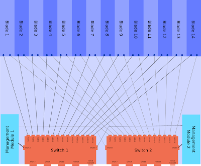
The CIGESM is a Cisco switch with 20 Gigabit Ethernet ports, these are:

  • 4 Physical ports on the back of the chassis.

  • 14 Ports connecting to the individual blades.

  • 2 Ports connecting to the internal Management Module for managing the switch via the chassis web interface.


Each of the blades is dual homed into the two CIGESM modules.

This architecture of a single blade center is shown below, click for larger version (warning 400kb image). This one assumes two management modules and two CIGESMs.


Management


The blade center itself is configured via a web interface that runs on the management module (MM). To access this initially you connect a copper cable directly into the MM port (has a picture of a network next to it), give your laptop an address in the 192.168.70.0/25 range and browse to 192.168.70.126. The default login is USERID/PASSW0RD (zero).

The CIGESM is a layer 2 switch and has a defined management interface, with the command "management" under the SVI. The Blade Center Management Module (MM) will configure the IP address on this interface. You can change it on the Cisco CLI but it will probably get set back by the MM at some point in future, so set it to the same on both MM and CLI!

CIGESM Management SVI


If you want to change the management interface VLAN then you'll need to do the following:

  1. If the IP is changing then update the network settings via the blade center web interface first.

  2. Create the layer 2 VLAN (for applying config to ports 15/16).

  3. Create the layer 3 SVI.

  4. Run the command "management" under the layer 3 SVI.

  5. Delete the old management interface.


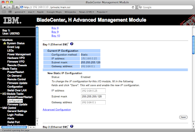
The web interface screen is shown below (names changed to protect the innocent), the network settings are under "I/O Module Tasks" -> "Configuration". Click for larger image:


An example of changing the management VLAN from 1 to 2, note the auto updates to Gi0/15&16 (explained later):

BC-Sw01(config-if)#int vlan 2
BC-Sw01(config-if)#management
Port Gi0/15 allowed vlan list updated to include vlan 2
Port Gi0/16 allowed vlan list updated to include vlan 2

BC-Sw01(config-if)#desc Management Interface
BC-Sw01(config-if)#ip address 192.168.0.25 255.255.255.128
BC-Sw01(config-if)#do show run interface vlan 2
interface Vlan2
description Management Interface
ip address 192.168.0.25 255.255.255.128
no ip route-cache
management
end


Internal Connections - Gi0/15 & Gi0/16


As shown in the architecture diagram above ports 15 & 16 are internal links to the management modules. These are used for communications between the MM and the switch, for instance if you click the "telnet" link within the MM web interface.

The management VLAN needs to be allowed over the internal link to the MM. Some parts of the configurations on these ports cannot be configured manually, such as access or native VLAN. These entries are set automatically when you specify an SVI for management.

If you try to reconfigure them on the CLI you'll see errors as below:
BC-Sw01(config)#int range gi0/15 - 16
BC-Sw01(config-if-range)#switchport access vlan 2
User prevented from modifing Ethernet port Gi0/15 access vlan

Command rejected: not allowed on this interface.User prevented from modifing Ethernet port Gi0/16 access vlan

Command rejected: not allowed on this interface.
BC-Sw01(config-if-range)#switchport trunk native vlan 2
User prevented from modifying Native VLAN on Port Gi0/15

Command rejected: not allowed on this interface.User prevented from modifying Native VLAN on Port Gi0/16

Command rejected: not allowed on this interface.
BC-Sw01(config-if-range)#switchport trunk allowed vlan 2
BC-Sw01(config-if-range)#


Read more...

Wednesday 17 February 2010

Creating a CRL for an OSX keychain CA

OSX has a handy keychain utility that can be used to create a CA among other things. I needed a CRL generated for my keychain-created CA in order to use certificate-based VPNs on a Netscreen box.


There are probably 101 ways of doing this, mine is:

Make a CA structure as per /opt/local/etc/openssl/openssl.cnf
(or alternately you could provide the suitable CLI options to openssl each time)


mkdir -p demoCA/private
echo 01 > demoCA/serial
echo 01 > demoCA/crlnumber


Locate your CA private key in the keychain utility, right click and export. This saves it as pkcs12 format.

Convert it to PEM format with:
openssl pkcs12 -nocerts -in My_Macbook_CA.p12 -out demoCA/private/cakey.pem


Edit it and delete the text above:
-----BEGIN RSA PRIVATE KEY-----


(this last step probably isn't necessary)

Export the CA certificate from keychain and change the format to PEM.

Then you can generate the CRL with:
openssl ca -gencrl -out crl.pem -cert exported_cert.pem


If you get any errors then check the paths, the default openssl config puts this in ./demoCA

Note that this creates a CRL valid for 30 days only with the default openssl.cnf, you probably want to increase this by editing /opt/local/etc/openssl/openssl.cnf and changing the default_crl_days value.


Read more...

Friday 12 February 2010

ToS DSCP Mappings

Reference table of ToS to DSCP mappings below.


PHB Value ToS Byte String DSCP Value
CS0 0 Routine 0
CS1 32 PRIORITY 8
AF11 40 10
AF12 48 12
AF13 56 14
CS2 64 IMMEDIATE 16
AF21 72 18
AF22 80 20
AF23 88 22
CS3 96 FLASH 24
AF31 104 26
AF32 112 28
AF33 120 30
CS4 128 FLASHOVERRIDE 32
AF41 136 34
AF42 144 36
AF43 152 38
CS5 160 CRITICAL 40
EF 184 46
CS6 192 INTERNETWORK CONTROL 48
CS7 224 NETWORK CONTROL 56


Read more...

Tuesday 9 February 2010

VTP Version 3 and MSTP Walkthrough.

This article assumes you are familiar with MSTP and VTP.

The latest incarnation of VTP version 3 is now available on versions of IOS from 12.2(50)SE3 onwards for 3560, 3750 and 2960s.

It supports distribution of two databases:

  • VLAN Database.

  • MSTP Vlan-to-MSTI mapping database.


Other than support for extended ID VLANs the VLAN database functionality is the same as previous versions. The MST mappings were not previously supported however and you had to manually create them on every device before. They show which VLANs are part of which spanning tree (or MSTI).

Another VTP version 3 function is to define a primary server that will not accept updates from any other device. This is meant to stop VTP bombs. When a switch is configured as the primary server it broadcasts itself on the network, the other VTP devices then create an entry with the MAC of this primary server and refuse to accept updates from any other device.

Implementation


The outputs here are from a sup720 running SXI3 IOS.

Previously you only had to set the VTP server, version and spanning-tree mode globally with commands such as:

RTR01(config)#vtp mode server
RTR01(config)#vtp version 3
RTR01(config)#spanning-tree mode mst


This configures the VTP status as follows, VTP server but leaves VTP support for MSTP in transparent mode.

RTR01#sh vtp status
VTP Version : 3 (capable)
VTP version running : 3
VTP Domain Name : VTPDOMAIN
VTP Pruning Mode : Disabled (Operationally Disabled)
VTP Traps Generation : Enabled
Device ID : 0200.0000.000a

Feature VLAN:
--------------
VTP Operating Mode : Server
Number of existing VLANs : 5
Number of existing extended VLANs : 0
Configuration Revision : 0
Primary ID : 0000.0000.0000
Primary Description :
MD5 digest : 0x00 0x00 0x00 0x00 0x00 0x00 0x00 0x00
0x00 0x00 0x00 0x00 0x00 0x00 0x00 0x00


Feature MST:
--------------
VTP Operating Mode : Transparent


To set the server as the primary use the command “vtp primary vlan”, in enable mode not config mode.

RTR01#vtp primary vlan
This system is becoming primary server for feature vlan
No conflicting VTP3 devices found.
Do you want to continue? [confirm]

This then shows the log message:

000087: Feb 8 14:12:55.145: %SW_VLAN-SW1_SP-4-VTP_PRIMARY_SERVER_CHG: 0200.0000.000a has become the primary server for the VLAN VTP feature


At this point only the configured primary server can send VTP updates to the networks. Clients should ignore updates from any other device. The VTP status is now updated to show the VTP primary server.

RTR01#sh vtp status
[snip]

Feature VLAN:
--------------
VTP Operating Mode : Primary Server
Number of existing VLANs : 5
Number of existing extended VLANs : 0
Configuration Revision : 1
Primary ID : 0200.0000.000a
Primary Description : RTR01
MD5 digest : 0x87 0xBB 0xDB 0xEC 0xE5 0x9F 0x9C 0xCA
0x75 0xCE 0x4A 0x67 0xA7 0x67 0xBF 0xDA


The VLAN database is being synced but the MST mappings are not. To set up the device as the primary server for MST requires a few more steps:

RTR01(config)#vtp mode server mst
Setting device to VTP Server mode for MST.
RTR01(config)#^Z
RTR01#vtp primary mst
This system is becoming primary server for feature mst
No conflicting VTP3 devices found.
Do you want to continue? [confirm]
000091: Feb 8 14:15:20.932: %SW_VLAN-SW1_SP-4-VTP_PRIMARY_SERVER_CHG: 0200.0000.000a has become the primary server for the MST VTP feature


Now the VTP status is updated to show the primary server for both VLAN and MST.

RTR01#show vtp status
VTP Version : 3 (capable)
VTP version running : 3
VTP Domain Name : VTPDOMAIN
VTP Pruning Mode : Disabled (Operationally Disabled)
VTP Traps Generation : Enabled
Device ID : 0200.0000.000a

Feature VLAN:
--------------
VTP Operating Mode : Primary Server
Number of existing VLANs : 5
Number of existing extended VLANs : 0
Configuration Revision : 1
Primary ID : 0200.0000.000a
Primary Description : RTR01
MD5 digest : 0x87 0xBB 0xDB 0xEC 0xE5 0x9F 0x9C 0xCA
0x75 0xCE 0x4A 0x67 0xA7 0x67 0xBF 0xDA


Feature MST:
--------------
VTP Operating Mode : Primary Server
Configuration Revision : 1
Primary ID : 0200.0000.000a
Primary Description : RTR01
MD5 digest : 0xC6 0x62 0xA6 0x96 0x7E 0x98 0x14 0xCB
0x80 0xA1 0xA6 0x2D 0x60 0x39 0x49 0x39


Any devices on the network running VTP version 3 in the correct VTP domain should now sync VLANs and MST mappings.

EDIT:
Should really include the client configuration as that has also changed slightly, the old way was:

vtp domain XXXX
vtp mode client


To get the MST mappings you also need to run the command:

vtp mode client mst


And because changing the MST mapping later causes a total STP reconvergence you should configure all the MST mappings on day 1, but more about that later :-)


Read more...

Saturday 6 February 2010

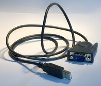
How to get USB serial adapters working in OSX

There are loads of cheap USB serial adapters around, the difficulty can be working out what chipset they use.

The easiest way to identify them is with a Linux live-CD.


Identify the chipset in Linux


You could just install the two drivers linked below, it won't do any harm if they're the wrong ones and there probably aren't that many different USB serial chipsets around so there's a good chance it'll work.

To make sure you'll need to identify the hardware using a Linux live CD. Ubuntu will do the job, also Knoppix. Pretty much any distribution should include a kernel with most of the drivers these days.

Boot up the live CD and plug in the USB serial adapter, load a terminal and run "dmesg" to see the system log. It should show the chipset that was detected and from there it's a simple google query to find the OSX driver.

Example output for this prolific one, drivers available from the manufacturor for OSX.
[ 6786.920018] usb 2-1: new full speed USB device using ohci_hcd and address 5
[ 6787.146546] usb 2-1: configuration #1 chosen from 1 choice
[ 6787.204328] usbcore: registered new interface driver usbserial
[ 6787.204346] USB Serial support registered for generic
[ 6787.204414] usbcore: registered new interface driver usbserial_generic
[ 6787.204417] usbserial: USB Serial Driver core
[ 6787.211673] USB Serial support registered for pl2303
[ 6787.211740] pl2303 2-1:1.0: pl2303 converter detected
[ 6787.243536] usb 2-1: pl2303 converter now attached to ttyUSB0
[ 6787.243559] usbcore: registered new interface driver pl2303
[ 6787.243562] pl2303: Prolific PL2303 USB to serial adaptor driver


This one is from FTDI who also have drivers for OSX.

[ 6922.152793] USB Serial support registered for FTDI USB Serial Device
[ 6922.152913] ftdi_sio 2-1:1.0: FTDI USB Serial Device converter detected
[ 6922.152944] usb 2-1: Detected FT232BM
[ 6922.152947] usb 2-1: Number of endpoints 2
[ 6922.152949] usb 2-1: Endpoint 1 MaxPacketSize 64
[ 6922.152952] usb 2-1: Endpoint 2 MaxPacketSize 64
[ 6922.152955] usb 2-1: Setting MaxPacketSize 64
[ 6922.154724] usb 2-1: FTDI USB Serial Device converter now attached to ttyUSB0
[ 6922.154752] usbcore: registered new interface driver ftdi_sio
[ 6922.154755] ftdi_sio: v1.5.0:USB FTDI Serial Converters Driver


Install the OSX Driver


Install the driver in OSX and connect the serial adapter, run "sudo dmesg" in a terminal and you should see the driver being loaded:
FTDIUSBSerialDriver:        0  4036001 start - ok


The serial port is presented as a character device entry in /dev/. You can read and write from this like any other character device with normal terminal commands, e.g.
echo "show run" > /dev/tty.USBSERIAL && cat /dev/tty.USBSERIAL


The serial drivers in OSX aren't consistent, some name the device as /dev/tty.USBSERIAL, but not all. The only devices that start with the string "tty." are the Bluetooth serial emulation ones (which all have Bluetooth in the filename) and the USB serial so it's easy to find them with
Matts-Macbook:~ matt$ ls /dev/tty.*
/dev/tty.Bluetooth-Modem
/dev/tty.Bluetooth-PDA-Sync
/dev/tty.usbserial-FTCC130A


Terminal Software


Then all you need is terminal software. You can try putty from macports but it won't talk to my serial ports. Screen is included in OSX and can be used to talk to the serial:
screen /dev/tty.USBSERIAL

There's also Zterm & macwise.

My preferred option is to install minicom from macports. It's not as pretty but it has the features I need:

  • It supports Xmodem, Zmodem and a whole host of other transfer protocols.

  • It can log the entire session.

  • It's free.

  • It has menus so you don't have to remember three million keyboard shortcuts.

  • It works.


What more do you need!


Read more...

Friday 5 February 2010

Cisco Gotchas - 1800 Virtual Ports

This is a (very late) addition to the article here.

Cisco 6500 doesn't directly limit the number of spanning-tree instances. It has limits on the number of virtual ports per line card.


A virtual port is a VLAN being forwarded on a trunk. So if you have 10 VLANs and 5 active trunks with no pruning then you have 50 virtual ports.

A 6500 is limited to 1800 virtual ports per line-card (with caveats, see below!).

If you have a full 48-port linecard and use PVST then you can only create 37 VLANs before you hit the limit. If you intend to go over this then either manually prune some VLANs or upgrade.

Some of the SX IOS versions have removed the virtual port limit on the newer linecards (6500 and 6700 series), however the per-chassis limits still apply.

The per-chassis limits are shown here.

They are 10000 for RPVST+ and 13000 for PVST+, updated in IOS 12.2(33)SXI to be 12000/15000 respectively.


If you want to get extra lifetime out of older linecards then look into using MST as it drastically simplifies the forwarding. Unless you have a need for a different STP topology for every VLAN then it's a great idea.


Read more...

Cisco Gotchas - Max VLANs and STP Instances

Cisco switches have separate limitations on:

  • The number of VLANs that can exist in the database.

  • The number of Spanning-Tree Instances that can run.


Cisco kit tends to use per-VLAN spanning-tree in which case the two values will be the same.


To understand the problem and solution requires knowledge of the different types of spanning-tree available, this subject is huge but very briefly the types are:

  1. Standard 802.1D Spanning-Tree

  2. PVST, Per-VLAN Spanning-Tree (ISL trunking only)

  3. PVST+, Per-VLAN Spanning-Tree plus (compatible with 802.1q trunks)

  4. Rapid PVST - RSTP version of PVST+

  5. MST - Multiple Spanning Tree


The limitations are as follows on switches running PVST, PVST+ or Rapid-PVST:

  • 2950 SI: Maximum 64 STP instances, Maximum 128 VLANs.

  • 2950 EI: Maximum 64 STP instances, Maximum 250 VLANS.

  • 3550, 3560, 3750: Maximum 128 STP instances, Maximum 1005 VLANs.

  • 6500: Based on logical ports. Article here.


If you exceed the number of VLANs then you'll get an error like this:
SPANTREE_VLAN_SW-2-MAX_INSTANCE: Platform limit of 64 STP instances exceeded. No instance created for VLANxxx


Solutions


There are a couple of workarounds:

  • Delete some VLANs!

  • Manually prune VLANs off the trunk links and set the switch to VTP mode transparent so it doesn't know about the extra VLANs.

  • Use MST instead of PVST.


MST is my preferred option. Most networks will only require 2 or 4 Spanning-Tree topologies anyway so it is wasteful to have STP running in every VLAN.


Read more...

Cisco Gotchas - 16 Unique Standby Groups

HSRP is configured in standby groups, each one having an identifier value in the switch configuration.

The acceptable range of values is 0-255 and you can create as many as you want. Cisco don't recommended using more than 500 on a 6500 series or 64 on the 3550.

There are limitations on the number of unique ID values you can assign however.


Each instance is configured using the standby command:

interface FastEthernet 0/10
ip address 10.0.0.3 255.255.255.0
standby 10 ip 10.0.0.1
standby 10 preempt


The gotcha is that you can create as many groups as you want, but you can only use 16 different values for the ID.

This is hardware/software specific, but it's not clear what hardware it's specific to. The Cisco FAQ says it only affects PFC2, but their bug tracker doesn't mention the PFC and has a "fixed in" entry indicating that it's not an issue with newer software.

So feel free to create as many unique IDs as you like, but when adding the 17th check the logs to make sure it's actually working!

Or you could use VSS and get rid of HSRP entirely.

The Cisco FAQ for this issue on the 6500 is here.
There is a bug open on the Cisco tracker, CSCdx32496.


Read more...

Monday 1 February 2010

Configure IOS by SNMP - Password Recovery

This is useful if you ever end up without a password for a router but you do know the SNMP read-write community values or usernames. It can save you the need to reboot a device and do a full password recovery, useful if the device is a thousand miles away and running some vital service.

You can load a configuration snippet into IOS from a TFTP server, triggered over SNMP.

The steps are:


Warning:

This can seriously b0rk your equipment and I accept no responsibility if it doesn't work for you. If your device is thousands of miles away, running critical services and you cannot login then your network has bigger issues than bodging the username on this one device! Don't do this unless you understand the possible consequences of blindly applying raw config to a Cisco device.


  1. Create a text file containing the config snippet.

  2. Run a TFTP server, on machine with IP 10.0.0.10 in this example.

  3. Set the value of iso.org.dod.internet.private.enterprises.cisco.lo cal.lsystem.hostConfigSet.10.0.0.10 to a string containing the filename from #2


The config snippet could be something like:

username cisco priv 15 password cisco


The command line for NET-SNMP tools snmpset is:

snmpset <router> <community> .iso.org.dod.internet.private.enterprises.cisco.local.lsystem.hostConfigSet.10.0.0.10 s <filename>


You can do a write mem via SNMP too if you want (but I wouldn't recommend it):

snmpset <router> <community> .iso.org.dod.internet.private.enterprises.cisco.local.lsystem.writeMem.0 i 1


If you can't login to a device and have absolutely no idea why not then it may not be as simple as adding a new local account. The specifics may be guessed at depending on how standardized your network is and you may be able to guess at the extra bits (heed the warning above), e.g.

no aaa new-model
username cisco priv 15 password cisco
line vty 0 15
login local
password cisco


Read more...