Thursday, 27 May 2010

MST - Multiple Spanning Tree - Don't change the mappings!

MST allows you to create spanning-tree instances and map VLANs into them.

Combined with VTP version 3 means you can advertise the MST mappings automatically, as shown here.

MST has the concept of regions.

Whether a switch is a member of a particular region depends on three things:

  • The configured MST region name.

  • The configured MST revision number.

  • The VLAN to MSTI mappings.


The entire VLAN to MSTI mapping isn't advertised in each BPDU but a checksum of the mapping table is.

So why do I care?


Because if you change the mappings, you change the region.

If you change the region that the root bridge belongs to, it's a topology change and you trigger a total STP re-convergence.


So if you're in a live network and you tweak the VLAN-to-MSTI mappings then you'll cause a complete outage. If it's running VTPv3 then the outage will be longer as the change ripples through the network and switches "re-join" the region.

The solution


The solution in this case is fairly easy, set up all your mappings on day 1 and stick to them!

If you've two switches then you're best off finding a suitable way to distribute the VLANs, e.g.

MSTI 1 - VLANS 1 to 1999 - Root bridge SW1
MSTI 2 - VLANS 2000 to 4096 - Root bridge SW2

Then make sure you set up HSRP/VRRP in future to match where the MSTI is rooted for each particular VLAN.

Read more...

Wednesday, 26 May 2010

Bundling Frame Relay Links

Frame-relay study time!

There are several ways to bundle links together in frame-relay:

  1. Frame-relay Multilink - FRF.16

  2. PPP Multilink


FRF16 requires configuration all along the path, so the service provider must support it. PPP multilink can be used on any frame-relay links and doesn't require anything from the SP.

Frame-relay Multilink - FRF.16


I'll be using the incredibly complicated topology shown below. To keep it simple the two routers are directly connected.


By default the "encapsulation frame-relay" command configures a device as a frame-relay DTE and two DTE's back-to-back won't talk. They'll both be sending LMI status enquiries but with no DCE to answer to tell them which DLCI is active, neither router will send any traffic. Using the "no keepalive" command brings the links up and stops the LMI messaging (which transmits every 6 keepalive cycles by default).


The configs are:


hostname R1
!
interface MFR1
ip address 192.168.0.1 255.255.255.0
no keepalive
frame-relay interface-dlci 100
!
interface Serial0/0
encapsulation frame-relay MFR1
clock rate 2000000
!
interface Serial0/1
encapsulation frame-relay MFR1
clock rate 2000000

hostname R2
!
interface MFR1
ip address 192.168.0.2 255.255.255.0
no keepalive
frame-relay interface-dlci 100
!
interface Serial0/0
encapsulation frame-relay MFR1
!
interface Serial0/1
encapsulation frame-relay MFR1


You can check the multilink status as below:

R1#show frame-relay multilink
Bundle: MFR1, State = up, class = A, fragmentation disabled
BID = MFR1
Bundle links:
Serial0/1, HW state = up, link state = Up, LID = Serial0/1
Serial0/0, HW state = up, link state = Up, LID = Serial0/0


PPP Multilink


In this case I've added a frame-relay switch in the middle.


It's providing two separate VCs and they are being bundled together at either end using PPP multilink. Configs are below:


hostname R1
!
interface Serial0/0
encapsulation frame-relay
frame-relay interface-dlci 102 ppp Virtual-Template1
!
interface Serial0/1
encapsulation frame-relay
frame-relay interface-dlci 304 ppp Virtual-Template1
!
interface Virtual-Template1
ip address 192.168.0.1 255.255.255.0
ppp multilink


hostname R2
!
interface Serial0/0
encapsulation frame-relay
frame-relay interface-dlci 201 ppp Virtual-Template1
!
interface Serial0/1
encapsulation frame-relay
frame-relay interface-dlci 403 ppp Virtual-Template1
!
interface Virtual-Template1
ip address 192.168.0.2 255.255.255.0
ppp multilink


Don't need to disable the keepalives now as there's a FR switch responding to LMI status queries.

To test the bundle, use "show ppp multilink". The Virtual-Access interfaces are randomly generated by PPP from the virtual-template and may not always be the same.

R1#show ppp multilink

Virtual-Access4, bundle name is R2
Endpoint discriminator is R2
Bundle up for 00:05:50, total bandwidth 200000, load 1/255
Receive buffer limit 24384 bytes, frag timeout 1000 ms
0/0 fragments/bytes in reassembly list
0 lost fragments, 0 reordered
0/0 discarded fragments/bytes, 0 lost received
0x2 received sequence, 0x2 sent sequence
Member links: 2 (max not set, min not set)
Vi1, since 00:05:50
Vi2, since 00:05:50
No inactive multilink interfaces

R1#show int vi1
Virtual-Access1 is up, line protocol is up
Hardware is Virtual Access interface
Internet address is 192.168.0.1/24
MTU 1500 bytes, BW 100000 Kbit, DLY 100000 usec,
reliability 255/255, txload 1/255, rxload 1/255
Encapsulation PPP, LCP Open, multilink Open
Link is a member of Multilink bundle Virtual-Access4
PPPoFR vaccess, cloned from Virtual-Template1
Vaccess status 0x44
Bound to Serial0/0 DLCI 102, Cloned from Virtual-Template1, loopback not set

R1#show int vi2
Virtual-Access2 is up, line protocol is up
Hardware is Virtual Access interface
Internet address is 192.168.0.1/24
MTU 1500 bytes, BW 100000 Kbit, DLY 100000 usec,
reliability 255/255, txload 1/255, rxload 1/255
Encapsulation PPP, LCP Open, multilink Open
Link is a member of Multilink bundle Virtual-Access4
PPPoFR vaccess, cloned from Virtual-Template1
Vaccess status 0x44
Bound to Serial0/1 DLCI 304, Cloned from Virtual-Template1, loopback not set


Read more...

Monday, 24 May 2010

SNMP Trap on VSS Failover

One of the big things that Cisco VSS is missing is the ability to clearly see when it's failed over.

You set up your spanking new 6500 with 10Gig supervisors, plug it into your network management, lose one of the boxes and get a few traps about routing problems. What you really want is a big in-your-face message saying "HELP ME THE VSS JUST FAILED OVER OH MY GOD THE SKY IS FALLING!!11!one" and it's not there. It'd be fairly easy to miss that anything happened at all.

One fix is to use the Embedded Event Manager (EEM) and hook it on one of the syslog messages. There's no obvious "WAAAH HELP VSS JUST DIED" message in syslog either, but it does have a few that pop up on failover such as this one (which also occurs on first VSS bootup but I'm not too fussed about an extra trap in that case):

%PFREDUN-SW2_SPSTBY-6-ACTIVE: Initializing as Virtual Switch ACTIVE processor


EEM lets you create an action that runs when this message appears in the log, I'll make it send an SNMP trap and write a clearer syslog. The following code is beerware, feel free to re-use and re-distribute. I'd appreciate a beer if you meet me (or at least link this site):

event manager applet VSS_active_state_change
event syslog pattern ".*%PFREDUN-.*_SPSTBY-6-ACTIVE.*"
action 1.0 snmp-trap strdata "VSS Failover - New Active VSS Supervisor"
action 1.1 syslog priority alerts msg "VSS Failover - New Active VSS Supervisor"


Now you get an SNMP trap and a SYSLOG saying:

*May 24 19:49:36.267: %HA_EM-1-LOG: VSS_active_state_change: VSS Failover - New Active VSS Supervisor


You can change the %HA_EM to something else with the "facility XXX" option in the syslog line, but it doesn't seem to be present on the 6500 with SXI3 IOS.

This does need EEM traps enabled, or you still won't have any alerts:
snmp-server enable traps event-manager


Read more...

Monday, 22 March 2010

Basic PPPoE Lab

Configurations below for a PPPoE lab, directly connecting two routers. This uses the new broad-band access (bba) command instead of the old VPDN ones.


Client:
interface Dialer1
ip address 192.168.0.10 255.255.255.0
encapsulation ppp
dialer pool 1

interface FastEthernet0/0
pppoe-client dial-pool-number 1


Server:
interface Virtual-Template1
ip address 192.168.0.1 255.255.255.0

bba-group pppoe global
virtual-template 1

interface FastEthernet0/0
pppoe enable


Or to use DHCP, the client would be:
interface Dialer1
ip address dhcp
encapsulation ppp
dialer pool 1

interface FastEthernet0/0
pppoe-client dial-pool-number 1


And server config:
ip dhcp excluded-address 192.168.0.1

ip dhcp pool IP_POOL
network 192.168.0.0 255.255.255.0

interface Virtual-Template1
ip address 192.168.0.1 255.255.255.0
peer default ip address dhcp-pool IP_POOL

bba-group pppoe global
virtual-template 1

interface FastEthernet0/0
pppoe enable


Read more...

Thursday, 18 March 2010

Generate Strong Passwords from a Unix Box

Works from any form of unix that has a /dev/urandom and has uuencode installed.


head -n 2 /dev/urandom | uuencode -m -


Read more...

Saturday, 20 February 2010

IBM Blade Centers - CIGESM Configuration

There are lots of docs from IBM explaining the blade center architecture but it's a lot of information to filter through if you're only interested in the network side.

The blade center in this example holds 14 blades which are best thought of as individual physical servers. It can use the Cisco switching module called a Cisco Systems Intelligent Gigabit Ethernet Switch Module, or CIGESM. They do run IOS but they don't behave in quite the same as normal Cisco switches.

Architecture


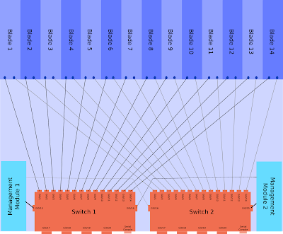
The CIGESM is a Cisco switch with 20 Gigabit Ethernet ports, these are:

  • 4 Physical ports on the back of the chassis.

  • 14 Ports connecting to the individual blades.

  • 2 Ports connecting to the internal Management Module for managing the switch via the chassis web interface.


Each of the blades is dual homed into the two CIGESM modules.

This architecture of a single blade center is shown below, click for larger version (warning 400kb image). This one assumes two management modules and two CIGESMs.


Management


The blade center itself is configured via a web interface that runs on the management module (MM). To access this initially you connect a copper cable directly into the MM port (has a picture of a network next to it), give your laptop an address in the 192.168.70.0/25 range and browse to 192.168.70.126. The default login is USERID/PASSW0RD (zero).

The CIGESM is a layer 2 switch and has a defined management interface, with the command "management" under the SVI. The Blade Center Management Module (MM) will configure the IP address on this interface. You can change it on the Cisco CLI but it will probably get set back by the MM at some point in future, so set it to the same on both MM and CLI!

CIGESM Management SVI


If you want to change the management interface VLAN then you'll need to do the following:

  1. If the IP is changing then update the network settings via the blade center web interface first.

  2. Create the layer 2 VLAN (for applying config to ports 15/16).

  3. Create the layer 3 SVI.

  4. Run the command "management" under the layer 3 SVI.

  5. Delete the old management interface.


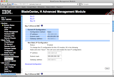
The web interface screen is shown below (names changed to protect the innocent), the network settings are under "I/O Module Tasks" -> "Configuration". Click for larger image:


An example of changing the management VLAN from 1 to 2, note the auto updates to Gi0/15&16 (explained later):

BC-Sw01(config-if)#int vlan 2
BC-Sw01(config-if)#management
Port Gi0/15 allowed vlan list updated to include vlan 2
Port Gi0/16 allowed vlan list updated to include vlan 2

BC-Sw01(config-if)#desc Management Interface
BC-Sw01(config-if)#ip address 192.168.0.25 255.255.255.128
BC-Sw01(config-if)#do show run interface vlan 2
interface Vlan2
description Management Interface
ip address 192.168.0.25 255.255.255.128
no ip route-cache
management
end


Internal Connections - Gi0/15 & Gi0/16


As shown in the architecture diagram above ports 15 & 16 are internal links to the management modules. These are used for communications between the MM and the switch, for instance if you click the "telnet" link within the MM web interface.

The management VLAN needs to be allowed over the internal link to the MM. Some parts of the configurations on these ports cannot be configured manually, such as access or native VLAN. These entries are set automatically when you specify an SVI for management.

If you try to reconfigure them on the CLI you'll see errors as below:
BC-Sw01(config)#int range gi0/15 - 16
BC-Sw01(config-if-range)#switchport access vlan 2
User prevented from modifing Ethernet port Gi0/15 access vlan

Command rejected: not allowed on this interface.User prevented from modifing Ethernet port Gi0/16 access vlan

Command rejected: not allowed on this interface.
BC-Sw01(config-if-range)#switchport trunk native vlan 2
User prevented from modifying Native VLAN on Port Gi0/15

Command rejected: not allowed on this interface.User prevented from modifying Native VLAN on Port Gi0/16

Command rejected: not allowed on this interface.
BC-Sw01(config-if-range)#switchport trunk allowed vlan 2
BC-Sw01(config-if-range)#


Read more...

Wednesday, 17 February 2010

Creating a CRL for an OSX keychain CA

OSX has a handy keychain utility that can be used to create a CA among other things. I needed a CRL generated for my keychain-created CA in order to use certificate-based VPNs on a Netscreen box.


There are probably 101 ways of doing this, mine is:

Make a CA structure as per /opt/local/etc/openssl/openssl.cnf
(or alternately you could provide the suitable CLI options to openssl each time)


mkdir -p demoCA/private
echo 01 > demoCA/serial
echo 01 > demoCA/crlnumber


Locate your CA private key in the keychain utility, right click and export. This saves it as pkcs12 format.

Convert it to PEM format with:
openssl pkcs12 -nocerts -in My_Macbook_CA.p12 -out demoCA/private/cakey.pem


Edit it and delete the text above:
-----BEGIN RSA PRIVATE KEY-----


(this last step probably isn't necessary)

Export the CA certificate from keychain and change the format to PEM.

Then you can generate the CRL with:
openssl ca -gencrl -out crl.pem -cert exported_cert.pem


If you get any errors then check the paths, the default openssl config puts this in ./demoCA

Note that this creates a CRL valid for 30 days only with the default openssl.cnf, you probably want to increase this by editing /opt/local/etc/openssl/openssl.cnf and changing the default_crl_days value.


Read more...