Showing posts with label vpn. Show all posts

Friday, 23 October 2009

ASA Site-to-Site VPN Using Certificates from OpenSSL

To provide increased security over pre-shared keys you can authenticate VPN endpoints using certificates. Ideally this would be using a full PKI solution but a simpler method is available if you don't need revocation.

This guide is for the Cisco ASA. As with most things it's a doddle in the ASDM because you can take full advantage of the GUI and be prompted for each step, however I'll show the CLI commands.


I'll use OpenSSL as a CA, following on from the previous article. There is a Cisco guide for using Microsofts CA (search for "asa site-to-site vpn certificate microsoft" if the link dies), but OpenSSL works just as well. This guide pretty much mirrors the Microsoft one above except for the editing of certificates and OpenSSL commands used to sign the certs.

The ASA can run it's own CA, however it seems aimed squarely at supporting remote user VPNs, it doesn't support signing CSRs and the user certificates it outputs are passcode protected so not usable by another ASA in a site-to-site VPN. If Cisco include that functionality it'd be very useful, if they add SCEP features to allow enrollment of devices then it'll be very handy indeed.


The procedure is:
  1. Install the CA public key onto the ASA.
  2. Generate a Certificate Signing Request (CSR) on the ASA.
  3. Sign the CSR using the CA.
  4. Install the signed certificate onto the ASA.
  5. Configure the VPN.


1. Install the CA public key onto the ASA


If you've followed the directions from the previous article then the public key is called cacert.pem, open this file in a text editor (wordpad rather than notepad if using Windows). On the ASA configure a CA trust point for terminal enrollment (pasting the key into the terminal), the authenticate command will then prompt you to paste the key:
crypto ca trustpoint Test_CA
enrollment terminal

crypto ca authenticate Test_CA
* At this point you'll be prompted to paste the CA public key (from cacert.pem) *


That's it, the ASA will now trust keys signed by your CA.

2. Generate a Certificate Signing Request (CSR) on the ASA.


You could just use the general keys for this but I'd make a specific key for each VPN. You then need a trustpoint where you can fine tune the certificate options. The enroll command will output the key to console.
!Generate the RSA key pair
crypto key generate rsa label FW1-Key modulus 1024

!Configure a trustpoint for the signed certificate
crypto ca trustpoint FW1-Key-trustpoint
enrollment terminal
fqdn 10.0.0.1
subject-name CN=10.0.0.1
keypair FW1-Key
crl configure

!output the CSR to console
crypto ca enroll FW1-Key-trustpoint


Copy this key into a text editor. It'll need the format changed slightly, by default the ASA outputs keys like:
MIIBnicE+P+jvc8JQBSbElTZUH8e7ULzXt8KWZQH6M/0U70wp6lqH6caHeCfDgKW
QIDAQABoDMwMQYJKoZIhbvHyAplT4ToJAATL7GwRhXqcmIpxL8k3xjP3XMkzorMZ
mLZdV8X4byX7Z9MlIEU44iWF+nePEJc60RQRgqTiLPqZcyO8besQxh74FVLW5H40
FE1/FceBzgz4ImgXMcC+0DxrNNToS2wZQDoYo7uL5I6hc9KBiV8Ki0drPe7ZOu4G
Pwdq+Ah9axuXtDua8xPe6G1bRQ9dGCgE4NSeQPnSz380WNqv6TZNddZhERlTNDoX
lbDQG0v+k5zJpCktRYa+f18IvJJxY9pVlpD4WKvyRHdaQydtudPejObY9prIg3rU
Gn1aJyCv0mjgF/JH4wnbhXgNbxBk0J1alpIEupq6Xo=

---End - This line not part of the certificate request---

But you need to edit the key so it looks like this:
-----BEGIN CERTIFICATE REQUEST-----
MIIBnicE+P+jvc8JQBSbElTZUH8e7ULzXt8KWZQH6M/0U70wp6lqH6caHeCfDgKW
QIDAQABoDMwMQYJKoZIhbvHyAplT4ToJAATL7GwRhXqcmIpxL8k3xjP3XMkzorMZ
mLZdV8X4byX7Z9MlIEU44iWF+nePEJc60RQRgqTiLPqZcyO8besQxh74FVLW5H40
FE1/FceBzgz4ImgXMcC+0DxrNNToS2wZQDoYo7uL5I6hc9KBiV8Ki0drPe7ZOu4G
Pwdq+Ah9axuXtDua8xPe6G1bRQ9dGCgE4NSeQPnSz380WNqv6TZNddZhERlTNDoX
lbDQG0v+k5zJpCktRYa+f18IvJJxY9pVlpD4WKvyRHdaQydtudPejObY9prIg3rU
Gn1aJyCv0mjgF/JH4wnbhXgNbxBk0J1alpIEupq6Xo=
-----END CERTIFICATE REQUEST-----


3. Sign the CSR using the CA.


To sign the key, copy it onto the system you've installed OpenSSL as per the previous guide. Use the following command to sign the CSR, mine's saved in a text file as "FW1-req.txt":
openssl ca -in FW1-req.txt -out FW1-signed.txt


4. Install the signed certificate onto the ASA.


To copy this certificate back to the ASA, import it for the trustpoint created earlier:
crypto ca import FW1-Key-trustpoint certificate
* Paste in the edited key as per above *


5. Configure the VPN.


The authentication method is configured in the crypto map, this will appear as follows:

crypto map outside_map 1 match address outside_1_cryptomap
crypto map outside_map 1 set pfs group2
crypto map outside_map 1 set peer 10.0.0.2
crypto map outside_map 1 set transform-set ESP-AES-128-SHA
crypto map outside_map 1 set trustpoint FW1-Key-trustpoint
crypto map outside_map interface outside


The rest of the VPN configuration is the same as pre-shared keys. Congratulations, you've got a certificate based VPN! If it's not working then try with a PSK to verify that the VPN is configured correctly, if that doesn't work then welcome to the wonderful world of debugging VPNs.

Read more...

OpenSSL CA for VPN Certificates

The aim of this article is to provide some pointers to getting a certificate authority (CA) up and running with OpenSSL and provide a few handy commands for reference. This will be used in some future articles about certificate based VPNs.


To do certificate based VPNs you need a couple of things:
  • A Certificate Authority (CA) that your end devices trust.
  • Host certificates signed by the CA.

I'll use the manual signing procedure which is done in several steps:
  1. Install the CA public key on the end devices.
  2. Create a Certificate Signing Request (CSR) on each end device.
  3. Use the CA to sign the CSR.
  4. Install the signed certificate back onto the device.
  5. Configure the VPN to use that certificate for authentication.

I've used the Ubuntu docs project guide to setting up a CA, that can be found here.

Update - August 2012 - Because Ubuntu are redirecting that site to another page with a different domain name the SSL cert is being rejected by strict filtering systems, so I'm copy/pasting some of it here for reference. The following is taken from the link above:
Creating the Certificate Authority
First, create an initial working environment, for example within your home directory by issuing the following command from a terminal prompt:


cd && mkdir -p myCA/signedcerts && mkdir myCA/private && cd myCA
The above command will place you in a newly-created subdirectory of your home directory named myCA, and within this subdirectory, you should have two additional subdirectories named signedcerts and private.

Within this initial working environment, the significance of the subdirectories, and their contents is as follows:

~/myCA : contains CA certificate, certificates database, generated certificates, keys, and requests

~/myCA/signedcerts : contains copies of each signed certificate 

~/myCA/private : contains the private key

Next, create an initial certificate database in the ~/myCA subdirectory with the following command at a terminal prompt:

echo '01' > serial  && touch index.txt

Now create an initial caconfig.cnf file suitable for the creation of CA certificates. Using your favorite editor, edit the file ~/myCA/caconfig.cnf, and insert the following content into the file:

sudo nano ~/myCA/caconfig.cnf

# My sample caconfig.cnf file.
#
# Default configuration to use when one is not provided on the command line.
#
[ ca ]
default_ca      = local_ca
#
#
# Default location of directories and files needed to generate certificates.
#
[ local_ca ]
dir             = /home//myCA
certificate     = $dir/cacert.pem
database        = $dir/index.txt
new_certs_dir   = $dir/signedcerts
private_key     = $dir/private/cakey.pem
serial          = $dir/serial
#       
#
# Default expiration and encryption policies for certificates.
#
default_crl_days        = 365
default_days            = 1825
default_md              = md5
#       
policy          = local_ca_policy
x509_extensions = local_ca_extensions
#       
#
# Default policy to use when generating server certificates.  The following
# fields must be defined in the server certificate.
#
[ local_ca_policy ]
commonName              = supplied
stateOrProvinceName     = supplied
countryName             = supplied
emailAddress            = supplied
organizationName        = supplied
organizationalUnitName  = supplied
#       
#
# x509 extensions to use when generating server certificates.
#
[ local_ca_extensions ]
subjectAltName          = DNS:alt.tradeshowhell.com
basicConstraints        = CA:false
nsCertType              = server
#       
#
# The default root certificate generation policy.
#
[ req ]
default_bits    = 2048
default_keyfile = /home//myCA/private/cakey.pem
default_md      = md5
#       
prompt                  = no
distinguished_name      = root_ca_distinguished_name
x509_extensions         = root_ca_extensions
#
#
# Root Certificate Authority distinguished name.  Change these fields to match
# your local environment!
#
[ root_ca_distinguished_name ]
commonName              = MyOwn Root Certificate Authority
stateOrProvinceName     = NC
countryName             = US
emailAddress            = root@tradeshowhell.com
organizationName        = Trade Show Hell
organizationalUnitName  = IT Department
#       
[ root_ca_extensions ]
basicConstraints        = CA:true
 IMPORTANT: Make sure to adjust the obvious site-specific details in the file, such as the two instances of /home// under [ local_ca ] and [ req ]. Also change commonName, stateOrProvinceName countryName etc under [ root_ca_distinguished_name ] to personalize for your environment. For more information on the directives contained within this configuration file, use the man config command.

When you've edited the file to match your environment, save the file as ~/myCA/caconfig.cnf.

Next, you need to generate the Certificate Authority Root Certificate and Key, by issuing a few commands. First, do this:

export OPENSSL_CONF=~/myCA/caconfig.cnf
The previous command sets an environment variable, OPENSSL_CONF, which forces the openssl tool to look for a configuration file in an alternative location (in this case, ~/myCA/caconfig.cnf).

Now, generate the CA certificate and key with the following command:

openssl req -x509 -newkey rsa:2048 -out cacert.pem -outform PEM -days 1825
You should be prompted for a passphrase, and see output similar to this:


Generating a 2048 bit RSA private key
.................................+++
.................................................................................................+++
writing new private key to '/home/bshumate/myCA/private/cakey.pem'
Enter PEM pass phrase:
Verifying - Enter PEM pass phrase:
-----
Do not forget the passphrase used with the command above! You'll need it every time you want to generate and sign a new server or client certificate!

The above process will create a self-signed certificate using PEM format and RSA public/private key encryption. The certificate will be valid for 1825 days. The location, and purpose of the resultant files is as follows:

~/myCA/cacert.pem : CA public certificate

~/myCA/private/cakey.pem : CA private key

Optional Step
Strip the certificate from all its text to keep only the -CERTIFICATE- section to create a crt

openssl x509 -in cacert.pem -out cacert.crt
Creating a Self-Signed Server Certificate
Now that you have a Certificate Authority configured, you may use it to sign self-signed certificates. Prior to beginning the steps below, you may wish to encrypt the certificate's private key with a passphrase. The advantages of encrypting the key with a passphrase include protection of the certificate in the event it is stolen. 

The certificate cannot be used with SSL-enabled applications without entering the passphrase every time the SSL-enabled application is started. This condition, while being most secure, can present a problem: If the server must be started in an unattended manner as in the case of a computer restart, then no one will be available to enter the passphrase, and subsequently the server will not start. One way to eliminate this condition involves a trade-off in security: The key may be decrypted, to remove the passphrase necessity; thus SSL-enabled applications will start automatically, without a need for you to enter a passphrase.

To actually generate a self-signed certificate for use with an SSL application, follow this process:

Create the server configuration file, by editing ~/myCA/exampleserver.cnf with your favorite text editor. Add this example content:


#
# exampleserver.cnf
#

[ req ]
prompt                  = no
distinguished_name      = server_distinguished_name

[ server_distinguished_name ]
commonName              = tradeshowhell.com
stateOrProvinceName     = NC
countryName             = US
emailAddress            = root@tradeshowhell.com
organizationName        = My Organization Name
organizationalUnitName  = Subunit of My Large Organization
Be sure to change the values under server_distinguished_name especially the commonName value. The commonName value must match the host name, or CNAME for the host you wish to use the key for. If the commonName does not match the intended hostname, then host / certificate mismatch errors will appear in the client applications of clients attempting to access the server.

Once you've edited the file appropriately, save it as ~/myCA/exampleserver.cnf. Generate the server certificate, and key with the following commands:

export OPENSSL_CONF=~/myCA/exampleserver.cnf

The previous command sets an environment variable OPENSSL_CONF which forces the openssl tool to look for a configuration file in an alternative location (in this case, ~/myCA/exampleserver.cnf).

Now generate the certificate, and key:

openssl req -newkey rsa:1024 -keyout tempkey.pem -keyform PEM -out tempreq.pem -outform PEM

You should be prompted for a passphrase, and see output similar to this:


Generating a 1024 bit RSA private key
...++++++
...............++++++
writing new private key to 'tempkey.pem'
Enter PEM pass phrase:
Verifying - Enter PEM pass phrase:
-----
Don't forget the passphrase!

Next, you may translate the temporary private key into an unencrypted key by using the following command:

openssl rsa < tempkey.pem > server_key.pem

You should be prompted for the passphrase used above, and see the following output:


Enter pass phrase:
writing RSA key
If you wish to leave the key encrypted with a passphrase, simply rename the temporary key using the following command, instead of following the step above:

mv tempkey.pem server_key.pem

 Remember: If you use a server key encrypted with a passphrase, the passphrase will have to be entered each time the server application using the encrypted key is started. This means the server application will not start unless someone, or something enters the key.

Now you need to sign the server certificate with the Certificate Authority (CA) key using these commands:

export OPENSSL_CONF=~/myCA/caconfig.cnf

The previous command modifies the environment variable OPENSSL_CONF which forces the openssl tool to look for a configuration file in an alternative location (in this case, ~/myCA/caconfig.cnf to switch back to the CA configuration).

Then sign the certificate as follows:

openssl ca -in tempreq.pem -out server_crt.pem

You will be prompted for the passphrase of the CA key as created in the Certificate Authority setup from above. Enter this passphrase at the prompt, and you will then be prompted to confirm the information in the exampleserver.cnf, and finally asked to confirm signing the certificate. Output should be similar to this:


Using configuration from /home/bshumate/myCA/caconfig.cnf
Enter pass phrase for /home/bshumate/myCA/private/cakey.pem:
Check that the request matches the signature
Signature ok
The Subject's Distinguished Name is as follows
commonName            :PRINTABLE:'tradeshowhell.com'
stateOrProvinceName   :PRINTABLE:'NC'
countryName           :PRINTABLE:'US'
emailAddress          :IA5STRING:'root@tradeshowhell.com'
organizationName      :PRINTABLE:'Trade Show Hell'
organizationalUnitName:PRINTABLE:'Black Ops'
Certificate is to be certified until Jan  4 21:50:08 2011 GMT (1825 days)
Sign the certificate? [y/n]:y


1 out of 1 certificate requests certified, commit? [y/n]y
Write out database with 1 new entries
Data Base Updated
Remove the temporary certificate, and key files with the following command:

rm -f tempkey.pem && rm -f tempreq.pem

Congratulations! You now have a self-signed server application certificate, and key pair:

server_crt.pem : Server application certificate file

server_key.pem : Server application key file

END OF COPY/PASTE

The instructions should work for any Unix system with OpenSSL.

The only changes I've made to their configuration were the hostname/path/DN changes and to alter policy about which fields needed to be supplied in the CSRs. This is just to save filling out every field each time I want to change certificates in the lab.


[ local_ca_policy ]
commonName = supplied
stateOrProvinceName = optional
countryName = optional
emailAddress = optional
organizationName = optional
organizationalUnitName = optional


With your directory structure created as per that article, config file created and appropriate environmental variables set you have a functional CA.

Handy OpenSSL Commands


Generate the CA public and private keys:

openssl req -x509 -newkey rsa:1024 -out cacert.pem -outform PEM -days 1825

Show information on a certificate:

openssl x509 -text -in <CERT>

Show information in a CSR:

openssl req -text -noout -in <CSR>

Verify the signature of a CSR:

openssl req -text -noout -in <CSR> -verify

Sign a CSR:

openssl ca -in <CSR> -out <SIGNED-CERT>


Read more...

Monday, 28 September 2009

MPLS: EIGRP as CE-PE Routing Protocol

Following the OSPF sham links and OSPF as PE-CE routing protocol articles, this entry shows how to use EIGRP as the PE-CE routing protocol.

The network topology is as before.


EIGRP is fairly easy to configure in this case. The CE router is just configured as per a vanilla EIGRP network with no special entries needed, on router CE1:

CE1#show ip int brief | inc up
FastEthernet0/0 10.0.255.1 YES NVRAM up up
FastEthernet0/1 172.16.1.1 YES NVRAM up up
CE1#show run | section eigrp
router eigrp 1
network 10.0.0.0
network 172.16.0.0
no auto-summary


On the PE router it is fairly straightforward, EIGRP is configured with an "address-family ipv4 vrf VRFNAME" command. The bit to note is the "autonomous-system X" line which tells the router what EIGRP AS is running in the VRF.

PE1#show run | section eigrp
router eigrp 1
auto-summary
!
address-family ipv4 vrf VPN_ONE
redistribute bgp 65001 metric 10000 20 255 1 1500
network 10.0.255.0 0.0.0.3
no auto-summary
autonomous-system 1


Any show commands on the PE router must include the VRF statement, e.g.:

PE1#show ip eigrp vrf VPN_ONE neighbors
IP-EIGRP neighbors for process 1
H Address Interface Hold Uptime SRTT RTO Q Seq
(sec) (ms) Cnt Num
0 10.0.255.1 Fa0/0 11 00:06:48 6 200 0 5


As with OSPF (solved by sham links), there is potential for problems with EIGRP if you have backdoor links between sites. The administrative distance of EIGRP internal routes is 90 whereas the iBGP routes AD is 200. To avoid this the pre-bestpath cost BGP extended community value is used.

The Cisco article on the cost community is here. Basically it allows the BGP routing decision process to be overridden by the cost community value which is split into two parts, the first being called the POI (Point-of-Insertion) which is the position in the routing process (e.g. before the normal BGP decision hooks such as weight, local pref, route origin) and the second part being a value that is copied from the EIGRP composite metric. This allows routes to be chosen based purely on the EIGRP metric and BGP factors are ignored.

Unlike sham links this is automatically enabled, here is the route to 172.16.2.0 as seen by BGP:

PE1#show ip bgp vpnv4 vrf VPN_ONE 172.16.2.0
BGP routing table entry for 1:1:172.16.2.0/24, version 11
Paths: (1 available, best #1, table VPN_ONE)
Not advertised to any peer
Local
10.255.255.52 (metric 129) from 10.255.255.52 (10.255.255.52)
Origin incomplete, metric 100, localpref 100, valid, internal, best
Extended Community: RT:1:1 Cost:pre-bestpath:128:307200 0x8800:32768:0
0x8801:1:51200 0x8802:65281:256000 0x8803:65281:1500
mpls labels in/out nolabel/23

The route is then received on CE1 with an advertised metric of 307200:
CE1#show ip eigrp top 172.16.2.0 255.255.255.0
IP-EIGRP (AS 1): Topology entry for 172.16.2.0/24
State is Passive, Query origin flag is 1, 1 Successor(s), FD is 332800
Routing Descriptor Blocks:
10.0.255.2 (FastEthernet0/0), from 10.0.255.2, Send flag is 0x0
Composite metric is (332800/307200), Route is Internal
Vector metric:
Minimum bandwidth is 10000 Kbit
Total delay is 3000 microseconds
Reliability is 255/255
Load is 1/255
Minimum MTU is 1500
Hop count is 2


Read more...

Saturday, 19 September 2009

MPLS: OSPF as PE-CE Routing Protocol

This article shows a basic configuration for using OSPF as the PE-CE routing protocol.

It follows on from the basic VRFs entry and uses the same network topology, with a couple of networks added to represent each sites internal LAN.

OSPF uses a hierarchical network structure where normally all areas would be connected directly to area 0. In the case of MPLS VPNs, there is always a redistribution to and from BGP in the middle of the network. The way MPLS is implemented avoids these routes being seen as external by using the concept of an MPLS VPN Superbackbone above area 0.

The OSPF network looks as below:


In a vanilla network assuming redistribution was set up everywhere, 172.16.1.0/24 (sourced at CE1) would be redistributed back to OSPF by PE2 as a type-5 external route.

In this case is PE1 redistributes the route from OSPF into BGP and adds extended communities to inform it's peer about the OSPF attributes of the route. The image below shows a capture of the BGP update message from PE1 advertising the 172.16.1.0 route (CE1 LAN). Note the extended attibutes in the update message, you can also see the label mappings advertised in the NRLI section.


PE2 can then take this information and rebuild the route advertisement as an OSPF type-3 (summary) LSA. The output below shows how PE2 receives the route from MP-BGP, containing the domain ID (corresponds to the OSPF process ID), route type (format area:type:option) and the advertising router ID.


PE2#show ip bgp vpnv4 vrf VPN_ONE 172.16.1.0
BGP routing table entry for 1:1:172.16.1.0/24, version 32
Paths: (1 available, best #1, table VPN_ONE)
Flag: 0x820
Not advertised to any peer
Local
10.255.255.51 (metric 129) from 10.255.255.51 (10.255.255.51)
Origin incomplete, metric 10, localpref 100, valid, internal, best
Extended Community: RT:1:1 OSPF DOMAIN ID:0x0005:0x000000640200
OSPF RT:0.0.0.0:3:0 OSPF ROUTER ID:10.254.254.51:0

mpls labels in/out 23/26


The OSPF metric is copied to/from the BGP MED value.

This route ends up in CE2 as an OSPF Summary (type-3 LSA):

CE2#show ip ospf database summary 172.16.1.0

OSPF Router with ID (172.16.2.1) (Process ID 100)

Summary Net Link States (Area 0)

Routing Bit Set on this LSA
LS age: 618
Options: (No TOS-capability, DC, Downward)
LS Type: Summary Links(Network)
Link State ID: 172.16.1.0 (summary Network Number)
Advertising Router: 10.254.254.52
LS Seq Number: 80000001
Checksum: 0x5167
Length: 28
Network Mask: /24
TOS: 0 Metric: 10


The relevant configurations for one half of the network is below (CE1/PE1), the other half is configured in the same way but with different IP addresses. No configuration is needed on the P routers as they purely switch based on labels arranged by the PE routers, P routers don't care about the customer VPNs.

It's worth noting that all the funky business is going on at the PE router which would be managed by the service provider and not accessible to the customer.

PE1

ip vrf VPN_ONE
rd 1:1
route-target export 1:1
route-target import 1:1

interface Loopback1
ip vrf forwarding VPN_ONE
ip address 10.254.254.51 255.255.255.255

interface FastEthernet0/0
description To CE1
ip vrf forwarding VPN_ONE
ip address 10.0.255.2 255.255.255.252

router ospf 100 vrf VPN_ONE
router-id 10.254.254.51
redistribute bgp 65001 metric 10 subnets
network 10.0.255.2 0.0.0.0 area 0

router bgp 65001
[snip - see previous articles for full BGP config]
!
address-family ipv4 vrf VPN_ONE
redistribute connected
redistribute ospf 100 vrf VPN_ONE metric 10 match internal external 1 external 2
exit-address-family


CE1
interface FastEthernet0/0
description To PE1
ip address 10.0.255.1 255.255.255.252

interface FastEthernet0/1
ip address 172.16.1.1 255.255.255.0

router ospf 100
log-adjacency-changes
network 10.0.255.1 0.0.0.0 area 0
network 172.16.1.1 0.0.0.0 area 101


Read more...

Monday, 8 June 2009

Checkpoint to Cisco VPNs #2

This is part 2 of the article started here. I'll be creating traditional mode VPN rules, because they are less abstracted than VPN communities and a bit easier to understand (in my opinion). There are some complications*.

To follow a similar methodology to that used on the Cisco router, the steps are as follows:
  1. Define the ISAKMP (phase 1) policy.
  2. Define the IPsec (phase 2) policy.
  3. Create the firewall rule specifying traffic to pass over the VPN.
  4. Define the encryption domains.

Checkpoint doesn't really have a concept of applying the crypto map to an interface as with Cisco. The Cisco concept of a crypto map is close to the encryption domains on Checkpoint.


1. Define the ISAKMP (phase 1) policy.

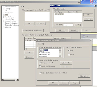
In Checkpoint the ISAKMP configuration is applied to an "interoperable device" object created for the Cisco VPN gateway. Edit your interoperable device and select "traditional mode configuration" on the "VPN" page to open the ISAKMP properties as shown here:

You configure encryption and integrity, specify to use a pre-shared secret (although you won't be able to enter one just yet) and in the "Advanced" options you can specify DH and lifetimes.

Be careful as the Cisco and Checkpoint default lifetimes do not match.

In practice, ISAKMP can negotiate new keys when the old ones are due to expire but best to make them match anyway to keep things tidy.


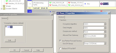
2. Define the IPsec (phase 2) policy.
3. Create the firewall rule specifying traffic to pass over the VPN.

IPSec policy is defined under the actual firewall rule which also specifies the interesting traffic. Create a rule allowing the VPN traffic through the firewall (using pre-NAT addresses) and set the action to be "Encrypt"*. Double click on "Encrypt" and you can edit the IPSec settings for the connection.

In this case we're using 3DES/MD5, DH group 2 and specifying which interoperable device the VPN is talking to.

The traffic being allowed is between 10.0.0.0/24 (local) and 172.16.0.0/24 (remote) in either direction and Any protocol.


4. Define the encryption domains.

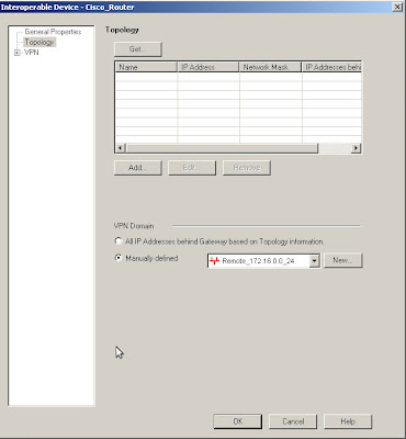
The encryption domains on Checkpoint are defined as properties of the gateway objects. Edit the interoperable device and open the "Toplogy" page, you can either manually set the topology or use another object to represent the encryption domain.

Here I am using the Remote_172.16.0.0_24 network object to define the Cisco end of the VPN encryption domain.

If you do destination NAT then the encryption domain is the post-NAT address as opposed to the firewall rules which must contain the pre-NAT address.


So that's the remote encryption domain defined, the local encryption domain is specified in the Checkpoint gateway object in the same way. The best way to do this is with a group, so that you can easily add further subnets in future if needed.


There is just one thing missing from the above, the shared key. This is actually defined on your local Checkpoint object rather than the remote peer's object. The reason I put this last is that the peer name won't show up until you've configured the interoperable device properties.

Edit your own Checkpoint enforcement module and open the VPN "Traditional mode configuration", then use the "Edit Secrets" button and you should see an entry for each of your VPN peers that have the "Pre-Shared Secret" box ticked.

Simply select the peer and enter the secret, "cisco" in this case.


Now having said all of the above, I will also say that making these systems interact nicely is a tricky business and you may find that it doesn't work even if you've followed these instructions to the letter.

Part 3 of this series of articles will include some troubleshooting methods to try and help fix any problems.


* Note: Checkpoint firewall policies are either in traditional VPN mode or simplified VPN mode which uses communities rather than the rules shown above.

If you don't have the "Encrypt" option in the Action column or if you have a "VPN" column then you're using a simplified VPN policy and cannot create traditional mode VPNs. Unfortunately you cannot convert a policy from simplified mode to traditional so your options are either to create a new policy from scratch, specifying "traditional" when you create it, or to use VPN communities instead.

Read more...

Sunday, 24 May 2009

Checkpoint to Cisco VPNs #1

Article #1 - Intro & Cisco Setup.

To show some of the finer points of Checkpoint VPNs I'll rig up a test lab with a site-to-site VPN linking a Cisco IOS router and a Checkpoint R65 splat box.

This article is not intended to be a general VPN introduction, rather the specifics of Checkpoint/Cisco interaction.


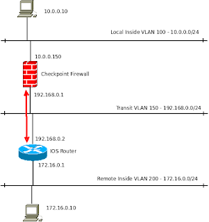
The network will look like this:


The local end is using 10.0.0.0/24, the Smart Center sits in this subnet.

The VPN traffic is shown by the red arrow. I'm using a transit network, VLAN 150 - 192.168.0.0/24 but this will probably be the internet in most cases.

The first VPN is going to be very simple, no NAT involved anywhere.


Cisco IOS Setup

In this case we need a static route configured on the IOS router to ensure traffic for the remote LAN goes out of the correct interface:
ip route 10.0.0.0 255.255.255.0 192.168.0.2
In reality you may not need this as for internet-based site-to-site VPNs the routers default route often does the job.

Now the five steps to create a VPN, handy bit of ISCW revision!
  1. Define the ISAKMP (phase 1) policy.
  2. Define the IPsec (phase 2) policy.
  3. Create the crypto ACL specifying interesting traffic.
  4. Make the crypto map to bind it all together.
  5. Apply the crypto map to an interface.

1 - ISAKMP policy

crypto isakmp policy 10
encr aes 256
hash sha
authentication pre-share
group 2
crypto isakmp key cisco address 192.168.0.1

2 - IPsec policy
crypto ipsec transform-set TESTSET esp-aes 256 esp-sha-hmac

3 - Crypto ACL
Define here what traffic should be encrypted.
ip access-list extended VPN_INTERESTING_TRAFFIC
permit ip 172.16.0.0 0.0.0.255 10.0.0.0 0.0.0.255 log

4 - Crypto Map.

 crypto map VPN_MAP 10 ipsec-isakmp
set peer 192.168.0.1
set transform-set TESTSET
set pfs group2
match address VPN_INTERESTING_TRAFFIC


5 - Apply to an interface

Cisco_Router(config)#interface fastethernet 0/0
Cisco_Router(config-if)#crypto map VPN_MAP
*Mar 1 00:25:33.187: %CRYPTO-6-ISAKMP_ON_OFF: ISAKMP is ON


If you see the "ISAKMP is ON" message then it's looking good. If you get errors then check whether your hardware and software is supported, as an example some of the 8xx series routers cannot do AES encryption and I don't think IPsec is supported on any of the standard IOS images.

Part 2 goes over configuration of the Checkpoint end.

Read more...