Showing posts with label bgp. Show all posts

Saturday, 19 September 2009

MPLS: OSPF as PE-CE Routing Protocol

This article shows a basic configuration for using OSPF as the PE-CE routing protocol.

It follows on from the basic VRFs entry and uses the same network topology, with a couple of networks added to represent each sites internal LAN.

OSPF uses a hierarchical network structure where normally all areas would be connected directly to area 0. In the case of MPLS VPNs, there is always a redistribution to and from BGP in the middle of the network. The way MPLS is implemented avoids these routes being seen as external by using the concept of an MPLS VPN Superbackbone above area 0.

The OSPF network looks as below:


In a vanilla network assuming redistribution was set up everywhere, 172.16.1.0/24 (sourced at CE1) would be redistributed back to OSPF by PE2 as a type-5 external route.

In this case is PE1 redistributes the route from OSPF into BGP and adds extended communities to inform it's peer about the OSPF attributes of the route. The image below shows a capture of the BGP update message from PE1 advertising the 172.16.1.0 route (CE1 LAN). Note the extended attibutes in the update message, you can also see the label mappings advertised in the NRLI section.


PE2 can then take this information and rebuild the route advertisement as an OSPF type-3 (summary) LSA. The output below shows how PE2 receives the route from MP-BGP, containing the domain ID (corresponds to the OSPF process ID), route type (format area:type:option) and the advertising router ID.


PE2#show ip bgp vpnv4 vrf VPN_ONE 172.16.1.0
BGP routing table entry for 1:1:172.16.1.0/24, version 32
Paths: (1 available, best #1, table VPN_ONE)
Flag: 0x820
Not advertised to any peer
Local
10.255.255.51 (metric 129) from 10.255.255.51 (10.255.255.51)
Origin incomplete, metric 10, localpref 100, valid, internal, best
Extended Community: RT:1:1 OSPF DOMAIN ID:0x0005:0x000000640200
OSPF RT:0.0.0.0:3:0 OSPF ROUTER ID:10.254.254.51:0

mpls labels in/out 23/26


The OSPF metric is copied to/from the BGP MED value.

This route ends up in CE2 as an OSPF Summary (type-3 LSA):

CE2#show ip ospf database summary 172.16.1.0

OSPF Router with ID (172.16.2.1) (Process ID 100)

Summary Net Link States (Area 0)

Routing Bit Set on this LSA
LS age: 618
Options: (No TOS-capability, DC, Downward)
LS Type: Summary Links(Network)
Link State ID: 172.16.1.0 (summary Network Number)
Advertising Router: 10.254.254.52
LS Seq Number: 80000001
Checksum: 0x5167
Length: 28
Network Mask: /24
TOS: 0 Metric: 10


The relevant configurations for one half of the network is below (CE1/PE1), the other half is configured in the same way but with different IP addresses. No configuration is needed on the P routers as they purely switch based on labels arranged by the PE routers, P routers don't care about the customer VPNs.

It's worth noting that all the funky business is going on at the PE router which would be managed by the service provider and not accessible to the customer.

PE1

ip vrf VPN_ONE
rd 1:1
route-target export 1:1
route-target import 1:1

interface Loopback1
ip vrf forwarding VPN_ONE
ip address 10.254.254.51 255.255.255.255

interface FastEthernet0/0
description To CE1
ip vrf forwarding VPN_ONE
ip address 10.0.255.2 255.255.255.252

router ospf 100 vrf VPN_ONE
router-id 10.254.254.51
redistribute bgp 65001 metric 10 subnets
network 10.0.255.2 0.0.0.0 area 0

router bgp 65001
[snip - see previous articles for full BGP config]
!
address-family ipv4 vrf VPN_ONE
redistribute connected
redistribute ospf 100 vrf VPN_ONE metric 10 match internal external 1 external 2
exit-address-family


CE1
interface FastEthernet0/0
description To PE1
ip address 10.0.255.1 255.255.255.252

interface FastEthernet0/1
ip address 172.16.1.1 255.255.255.0

router ospf 100
log-adjacency-changes
network 10.0.255.1 0.0.0.0 area 0
network 172.16.1.1 0.0.0.0 area 101


Read more...
Wednesday, 9 September 2009

MPLS Lab #3 -Simple VRFs

This follows on from the previous article part 2.

In this article I'll get the customer sites connected up in a very simple VRF.


The first step is to create a VRF for the customer sites to use. This is done by naming it on each PE router, assigning a route distinguisher (RD) and setting route targets (RT) for BGP to use. The simplest way to do this is to allocate the RD in the format AS:nn where AS is the customers autonomous system number, then to assign the same value to the RT.

In this case the customers AS will be 1 so the configuration is:

ip vrf VPN_ONE
rd 1:1
route-target export 1:1
route-target import 1:1


This creates the VRF on the two PE routers, to make use of them the interfaces leading to the CE routers have to be put into the VRF:

PE1#show run int fastEthernet 0/0
Building configuration...

Current configuration : 153 bytes
!
interface FastEthernet0/0
description To CE1
ip vrf forwarding VPN_ONE
ip address 10.0.255.2 255.255.255.252
end

PE2#show run int fastEthernet 0/0
Building configuration...

Current configuration : 153 bytes
!
interface FastEthernet0/0
description To CE2
ip vrf forwarding VPN_ONE
ip address 10.0.255.5 255.255.255.252
end


At this stage the CE routers can contact their directly connected PE router, but they cannot contact each other. They are also completely segregated from the backbone of the service providers network. They are given a default route via the PE router:

CE1#show ip route
[snip]
S* 0.0.0.0/0 [1/0] via 10.0.255.2


CE1 to PE1
Type escape sequence to abort.
Sending 5, 100-byte ICMP Echos to 10.0.255.2, timeout is 2 seconds:
!!!!!
Success rate is 100 percent (5/5), round-trip min/avg/max = 1/5/8 ms

CE1 to CE2
Type escape sequence to abort.
Sending 5, 100-byte ICMP Echos to 10.0.255.6, timeout is 2 seconds:
U.U.U
Success rate is 0 percent (0/5)
CE1#ping 10.0.0.9

CE1 to P1
Type escape sequence to abort.
Sending 5, 100-byte ICMP Echos to 10.0.0.9, timeout is 2 seconds:
U.U.U
Success rate is 0 percent (0/5)


To allow communication between the two customer sites (the two CE routers), we need to have MP-BGP advertising the vpnv4 routes between the two PE routers. Because there aren't really any customer sites yet, just the links that are directly connected between CE and PE, we can "redistribute connected" routes on the PE routers so that MP-BGP advertises them with the RD for this customers VRF.

This is done as follows:

PE1#config term
Enter configuration commands, one per line. End with CNTL/Z.
PE1(config)#router bgp 65001
PE1(config-router)#address-family ipv4 vrf VPN_ONE
PE1(config-router-af)#redistribute connected

With the same on PE2. Now we can look at the BGP routes specific to this VPN and see the connected interfaces are being advertised:

PE1#show ip bgp vpnv4 vrf VPN_ONE
BGP table version is 17, local router ID is 10.255.255.51
Status codes: s suppressed, d damped, h history, * valid, > best, i - internal,
r RIB-failure, S Stale
Origin codes: i - IGP, e - EGP, ? - incomplete

Network Next Hop Metric LocPrf Weight Path
Route Distinguisher: 1:1 (default for vrf VPN_ONE)
*> 10.0.255.0/30 0.0.0.0 0 32768 ?
*>i10.0.255.4/30 10.255.255.52 0 100 0 ?

As the VRF instances on the two PE routers can now see each other, they are able to forward traffic between the two CE routers. The customer sites are now linked up:

CE1#ping 10.0.255.6

Type escape sequence to abort.
Sending 5, 100-byte ICMP Echos to 10.0.255.6, timeout is 2 seconds:
!!!!!
Success rate is 100 percent (5/5), round-trip min/avg/max = 8/11/16 ms


So a very basic network setup, two sites able to communicate over a WAN. The PE router configuration is given below, snipped for brevity. Points to note are:

  • VRF VPN_ONE defined.
  • OSPF running internal to the Service Provider WAN, not visible to CE1 attached to f0/0.
  • BGP running between PE1 and PE2, advertising vpnv4 routes to allow the VRF communications.

hostname PE1
!
ip vrf VPN_ONE
rd 1:1
route-target export 1:1
route-target import 1:1
!
interface Loopback0
ip address 10.255.255.51 255.255.255.255
!
interface FastEthernet0/0
description To CE1
ip vrf forwarding VPN_ONE
ip address 10.0.255.2 255.255.255.252
!
interface Serial0/0
description To P1
ip address 10.0.0.1 255.255.255.252
mpls ip
!
interface Serial0/1
description To P2
ip address 10.0.0.5 255.255.255.252
mpls ip
!
router ospf 1
router-id 10.255.255.51
network 10.0.0.0 0.255.255.255 area 0
!
router bgp 65001
bgp router-id 10.255.255.51
neighbor 10.255.255.52 remote-as 65001
neighbor 10.255.255.52 update-source Loopback0
!
address-family ipv4
neighbor 10.255.255.52 activate
exit-address-family
!
address-family vpnv4
neighbor 10.255.255.52 activate
neighbor 10.255.255.52 send-community extended
exit-address-family
!
address-family ipv4 vrf VPN_ONE
redistribute connected
exit-address-family


To try and show a bit more of the segregation that is now in place, look at the routing table on PE1. Note that it does not contain any information from the VRF VPN_ONE on router PE2 (such as the CE2 IP address of 10.0.255.6), also note that PE2 is not able to directly contact CE2, although it can contact it via the VRF "VPN_ONE":

PE1show ip route
Codes: C - connected, S - static, R - RIP, M - mobile, B - BGP
D - EIGRP, EX - EIGRP external, O - OSPF, IA - OSPF inter area
N1 - OSPF NSSA external type 1, N2 - OSPF NSSA external type 2
E1 - OSPF external type 1, E2 - OSPF external type 2
i - IS-IS, su - IS-IS summary, L1 - IS-IS level-1, L2 - IS-IS level-2
ia - IS-IS inter area, * - candidate default, U - per-user static route
o - ODR, P - periodic downloaded static route

Gateway of last resort is not set

10.0.0.0/8 is variably subnetted, 8 subnets, 2 masks
O 10.0.0.8/30 [110/128] via 10.0.0.2, 00:26:46, Serial0/0
O 10.0.0.12/30 [110/128] via 10.0.0.6, 00:26:46, Serial0/1
C 10.0.0.0/30 is directly connected, Serial0/0
C 10.0.0.4/30 is directly connected, Serial0/1
C 10.255.255.51/32 is directly connected, Loopback0
O 10.255.255.52/32 [110/129] via 10.0.0.6, 00:26:46, Serial0/1
[110/129] via 10.0.0.2, 00:26:46, Serial0/0
O 10.255.255.102/32 [110/65] via 10.0.0.6, 00:26:46, Serial0/1
O 10.255.255.101/32 [110/65] via 10.0.0.2, 00:26:46, Serial0/0
PE1ping 10.0.255.6

Type escape sequence to abort.
Sending 5, 100-byte ICMP Echos to 10.0.255.6, timeout is 2 seconds:
.....
Success rate is 0 percent (0/5)
PE1#ping vrf VPN_ONE ip 10.0.255.6

Type escape sequence to abort.
Sending 5, 100-byte ICMP Echos to 10.0.255.6, timeout is 2 seconds:
!!!!!
Success rate is 100 percent (5/5), round-trip min/avg/max = 4/6/8 ms


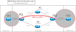
The following diagram should help make several things clear:


The first thing is that I'm a network engineer and not an artist for good reason!
The second is that we've now managed to overlay a customer network onto the service provider network, the two customer sites are segregated IP networks from the SP backbone. The network VPN_ONE is shown by the grey shaded areas and bounded by red.


Read more...

Sunday, 6 September 2009

MPLS Lab Part 2

Follows on from part 1.

Now to get MP-BGP up and running on the MPLS lab. BGP-4 (as described in RFC 1771) can only carry IPv4 prefixes. RFC 2858 adds multiprotocol capability to BGP-4, which is needed to work with the vpnv4 routes that MPLS uses.


vpnv4?
In an MPLS network you may have customers with overlapping IP address space. In order to provide unique addressing, a vpnv4 prefix is used consisting of a Route Distinguisher (RD) followed by the IP prefix. The RD is 64 bits and typically in format AS:nn (or IP:nn). For example if you use an RD of 65001:1 and your IP prefix is 10.0.255.0/24 then the vpnv4 prefix is 65001:1:10.0.255.0/24.


The reason things are like this is because you have many customers sharing the same WAN, they are seperated by an MPLS VPN between their sites. This is done by using MP-BGP relationships as shown in the diagram below:


In this case I'm just setting up a single customer so the network looks like this:


Firstly I'll set up vanilla BGP-4 between PE1 and PE2, specifying to use the loopback interfaces for the peer relationships:


PE1#sh run | section bgp
router bgp 65001
no synchronization
bgp router-id 10.255.255.51
bgp log-neighbor-changes
neighbor 10.255.255.52 remote-as 65001
neighbor 10.255.255.52 update-source Loopback0
no auto-summary


PE1#show run | section bgp
router bgp 65001
no synchronization
bgp router-id 10.255.255.51
bgp log-neighbor-changes
neighbor 10.255.255.52 remote-as 65001
neighbor 10.255.255.52 update-source Loopback0
no auto-summary


When watching the debugs this gives:

*Mar 1 00:15:42.659: BGP: 10.255.255.52 passive open to 10.255.255.51
*Mar 1 00:15:42.659: BGP: 10.255.255.52 went from Active to Idle
*Mar 1 00:15:42.659: BGP: 10.255.255.52 went from Idle to Connect
*Mar 1 00:15:42.659: BGP: 10.255.255.52 rcv message type 1, length (excl. header) 26
*Mar 1 00:15:42.659: BGP: 10.255.255.52 rcv OPEN, version 4, holdtime 180 seconds
*Mar 1 00:15:42.659: BGP: 10.255.255.52 went from Connect to OpenSent
*Mar 1 00:15:42.659: BGP: 10.255.255.52 sending OPEN, version 4, my as: 65001, holdtime 180 seconds
*Mar 1 00:15:42.659: BGP: 10.255.255.52 rcv OPEN w/ OPTION parameter len: 16
*Mar 1 00:15:42.659: BGP: 10.255.255.52 rcvd OPEN w/ optional parameter type 2 (Capability) len 6
*Mar 1 00:15:42.659: BGP: 10.255.255.52 OPEN has CAP
PE1#ABILITY code: 1, length 4
*Mar 1 00:15:42.659: BGP: 10.255.255.52 OPEN has MP_EXT CAP for afi/safi: 1/1
*Mar 1 00:15:42.659: BGP: 10.255.255.52 rcvd OPEN w/ optional parameter type 2 (Capability) len 2
*Mar 1 00:15:42.659: BGP: 10.255.255.52 OPEN has CAPABILITY code: 128, length 0
*Mar 1 00:15:42.659: BGP: 10.255.255.52 OPEN has ROUTE-REFRESH capability(old) for all address-families
*Mar 1 00:15:42.659: BGP: 10.255.255.52 rcvd OPEN w/ optional parameter type 2 (Capability) len 2
*Mar 1 00:15:42.659: BGP: 10.255.255.52 OPEN has CAPABILITY code: 2, length 0
*Mar 1 00:15:42.659: BGP: 10.255.255.52 OPEN has ROUTE-REFRESH capability(new) for all address-families
BGP: 10.255.255.52 rcvd OPEN w/ remote AS 65001
*Mar 1 00:15:42.659: BGP: 10.255.255.52 went from OpenSent to OpenConfirm
*Mar 1 00:15:42.659: BGP: 10.255.255.52 send message type 1, length (incl. header) 45
*Mar 1 00:15:42.663: BGP: 10.255.255.52 went from OpenConfirm to Established
*Mar 1 00:15:42.663: %BGP-5-ADJCHANGE: neighbor 10.255.255.52 Up


The neighbor relationship is up

PE1#sh ip bgp nei
BGP neighbor is 10.255.255.52, remote AS 65001, internal link
BGP version 4, remote router ID 10.255.255.52
BGP state = Established, up for 00:01:42
Last read 00:00:41, last write 00:00:41, hold time is 180, keepalive interval is 60 seconds
Neighbor capabilities:
Route refresh: advertised and received(old & new)
Address family IPv4 Unicast: advertised and received


Two important bits are missing, the neighbor does not show capability "Address family VPNv4 Unicast" and the afi/safi values in the debug output don't show support for VPNv4.


*Mar 1 00:15:42.659: BGP: 10.255.255.52 OPEN has MP_EXT CAP for afi/safi: 1/1


The Address Family Identifier (AFI) and Subsequent Address Family Identifier (SAFI) values can be found on the IANA website: AFI and SAFI. An AFI of 1 is IPv4, SAFI of 1 is NRLI for unicast forwarding and SAFI of 128 is for labelled VPN forwarding.

To activate the vpnv4 support, a bit more configuration is required:


PE1#show run | section bgp
router bgp 65001
bgp router-id 10.255.255.51
bgp log-neighbor-changes
neighbor 10.255.255.52 remote-as 65001
neighbor 10.255.255.52 update-source Loopback0
!
address-family ipv4
neighbor 10.255.255.52 activate
no auto-summary
no synchronization
exit-address-family
!
address-family vpnv4
neighbor 10.255.255.52 activate
neighbor 10.255.255.52 send-community extended
exit-address-family


router bgp 65001
bgp router-id 10.255.255.52
bgp log-neighbor-changes
neighbor 10.255.255.51 remote-as 65001
neighbor 10.255.255.51 update-source Loopback0
!
address-family ipv4
neighbor 10.255.255.51 activate
no auto-summary
no synchronization
exit-address-family
!
address-family vpnv4
neighbor 10.255.255.51 activate
neighbor 10.255.255.51 send-community extended
exit-address-family


Now the debug line in question shows:

*Mar 1 00:21:31.183: BGP: 10.255.255.52 OPEN has MP_EXT CAP for afi/safi: 1/128

And the neighbor capabilities are listed as:

PE1#show ip bgp neigh
BGP neighbor is 10.255.255.52, remote AS 65001, internal link
BGP version 4, remote router ID 10.255.255.52
BGP state = Established, up for 00:00:54
Last read 00:00:54, last write 00:00:54, hold time is 180, keepalive interval is 60 seconds
Neighbor capabilities:
Route refresh: advertised and received(old & new)
Address family IPv4 Unicast: advertised and received
Address family VPNv4 Unicast: advertised and received


This gives us working MP-BGP between the two PE routers, but nothing is actually being advertised over BGP just yet because there are no redistribute or network statements.


Read more...