Monday 28 September 2009

MPLS: EIGRP as CE-PE Routing Protocol

Following the OSPF sham links and OSPF as PE-CE routing protocol articles, this entry shows how to use EIGRP as the PE-CE routing protocol.

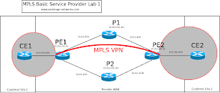
The network topology is as before.


EIGRP is fairly easy to configure in this case. The CE router is just configured as per a vanilla EIGRP network with no special entries needed, on router CE1:

CE1#show ip int brief | inc up
FastEthernet0/0 10.0.255.1 YES NVRAM up up
FastEthernet0/1 172.16.1.1 YES NVRAM up up
CE1#show run | section eigrp
router eigrp 1
network 10.0.0.0
network 172.16.0.0
no auto-summary


On the PE router it is fairly straightforward, EIGRP is configured with an "address-family ipv4 vrf VRFNAME" command. The bit to note is the "autonomous-system X" line which tells the router what EIGRP AS is running in the VRF.

PE1#show run | section eigrp
router eigrp 1
auto-summary
!
address-family ipv4 vrf VPN_ONE
redistribute bgp 65001 metric 10000 20 255 1 1500
network 10.0.255.0 0.0.0.3
no auto-summary
autonomous-system 1


Any show commands on the PE router must include the VRF statement, e.g.:

PE1#show ip eigrp vrf VPN_ONE neighbors
IP-EIGRP neighbors for process 1
H Address Interface Hold Uptime SRTT RTO Q Seq
(sec) (ms) Cnt Num
0 10.0.255.1 Fa0/0 11 00:06:48 6 200 0 5


As with OSPF (solved by sham links), there is potential for problems with EIGRP if you have backdoor links between sites. The administrative distance of EIGRP internal routes is 90 whereas the iBGP routes AD is 200. To avoid this the pre-bestpath cost BGP extended community value is used.

The Cisco article on the cost community is here. Basically it allows the BGP routing decision process to be overridden by the cost community value which is split into two parts, the first being called the POI (Point-of-Insertion) which is the position in the routing process (e.g. before the normal BGP decision hooks such as weight, local pref, route origin) and the second part being a value that is copied from the EIGRP composite metric. This allows routes to be chosen based purely on the EIGRP metric and BGP factors are ignored.

Unlike sham links this is automatically enabled, here is the route to 172.16.2.0 as seen by BGP:

PE1#show ip bgp vpnv4 vrf VPN_ONE 172.16.2.0
BGP routing table entry for 1:1:172.16.2.0/24, version 11
Paths: (1 available, best #1, table VPN_ONE)
Not advertised to any peer
Local
10.255.255.52 (metric 129) from 10.255.255.52 (10.255.255.52)
Origin incomplete, metric 100, localpref 100, valid, internal, best
Extended Community: RT:1:1 Cost:pre-bestpath:128:307200 0x8800:32768:0
0x8801:1:51200 0x8802:65281:256000 0x8803:65281:1500
mpls labels in/out nolabel/23

The route is then received on CE1 with an advertised metric of 307200:
CE1#show ip eigrp top 172.16.2.0 255.255.255.0
IP-EIGRP (AS 1): Topology entry for 172.16.2.0/24
State is Passive, Query origin flag is 1, 1 Successor(s), FD is 332800
Routing Descriptor Blocks:
10.0.255.2 (FastEthernet0/0), from 10.0.255.2, Send flag is 0x0
Composite metric is (332800/307200), Route is Internal
Vector metric:
Minimum bandwidth is 10000 Kbit
Total delay is 3000 microseconds
Reliability is 255/255
Load is 1/255
Minimum MTU is 1500
Hop count is 2


Read more...

Saturday 19 September 2009

OSPF Sham Links

If you install a backup link between sites in an MPLS VPN then you can run into problems as shown below.

This article follows on from OSPF as a PE-CE routing protocol and uses the same network layout.

I've set everything into area 0 to simplify things a bit, however there is now a serial link between the two customer sites. Topology is shown below:


Before the link is brought up the routing table on CE1 looks as follows, the important route is the 172.16.2.0 (CE2 site LAN) which is currently reached via the MPLS WAN:

CE1#show ip route

172.16.0.0/24 is subnetted, 2 subnets
C 172.16.1.0 is directly connected, FastEthernet0/1
O IA 172.16.2.0 [110/20] via 10.0.255.2, 00:01:15, FastEthernet0/0
10.0.0.0/8 is variably subnetted, 3 subnets, 2 masks
O E2 10.254.254.52/32 [110/10] via 10.0.255.2, 00:01:10, FastEthernet0/0
O IA 10.0.255.4/30 [110/20] via 10.0.255.2, 00:01:15, FastEthernet0/0
C 10.0.255.0/30 is directly connected, FastEthernet0/0


The link is brought up using 192.168.255.0/24 and OSPF is enabled across it. As it's a backup link the cost is set accordingly.


CE1#show run int s0/0
Building configuration...

Current configuration : 142 bytes
!
interface Serial0/0
description Backup Link to Site 2
ip address 192.168.255.1 255.255.255.0
ip ospf cost 30000
clock rate 2000000

CE1#show ip route
[snip]
172.16.0.0/24 is subnetted, 2 subnets
C 172.16.1.0 is directly connected, FastEthernet0/1
O 172.16.2.0 [110/30010] via 192.168.255.2, 00:00:51, Serial0/0
10.0.0.0/8 is variably subnetted, 4 subnets, 2 masks
O E2 10.254.254.51/32 [110/10] via 192.168.255.2, 00:00:51, Serial0/0
O E2 10.254.254.52/32 [110/10] via 10.0.255.2, 00:00:51, FastEthernet0/0
O 10.0.255.4/30 [110/30010] via 192.168.255.2, 00:00:51, Serial0/0
C 10.0.255.0/30 is directly connected, FastEthernet0/0
C 192.168.255.0/24 is directly connected, Serial0/0


The problem is that the remote site is now being routed via the backup link, which is a 2mbit line, when there is a 100mbit ethernet link available. The reason for this is due to the administrative distance.

There are two routes being advertised to CE1 for the 172.16.2.0 network, one via iBGP and one via OSPF. The administrative distance of iBGP is 200 and OSPF is 110 so the OSPF route is chosen. The bandwidth of the link isn't compared because of the order of route selection:
  1. Prefix Length.
  2. Administrative Distance (configured then default).
  3. Routing Protocol Metric.


The AD is compared before the metric so the routing process doesn't get as far as looking at the bandwidth of the link or the configured OSPF cost, it's already decided that OSPF is preferable to iBGP and will use it whatever.

The way around this is to use a Sham link. This is basically fudging the routing decision process by running an OSPF link across the MPLS WAN so that you have matching ADs and then can use the metric to decide which route is preferred.


The configuration is simple enough, you need a loopback with a /32 address on each PE router. That address must be advertised into the VRF across BGP. We've already got this with loopback 1 so the configuration is simply:

PE1#show run int loop1
Building configuration...

Current configuration : 96 bytes
!
interface Loopback1
ip vrf forwarding VPN_ONE
ip address 10.254.254.51 255.255.255.255
end
!
PE1#show run | section ospf
router ospf 100 vrf VPN_ONE
router-id 10.254.254.51
area 0 sham-link 10.254.254.51 10.254.254.52 cost 10

With the opposing configuration on PE2. The OSPF neighbors on PE1 then show an additional neighbor across the Sham Link:

PE1#show ip ospf 100 nei

Neighbor ID Pri State Dead Time Address Interface
10.254.254.52 0 FULL/ - - 10.254.254.52 OSPF_SL0
172.16.1.1 1 FULL/DR 00:00:34 10.0.255.1 FastEthernet0/0

PE1#show ip ospf 100 int
OSPF_SL0 is up, line protocol is up
Internet Address 0.0.0.0/0, Area 0
Process ID 100, Router ID 10.254.254.51, Network Type SHAM_LINK, Cost: 10


Now the routing table on CE1 shows that the MPLS WAN is being used for all traffic:

CE1#show ip route
[snip]
172.16.0.0/24 is subnetted, 2 subnets
C 172.16.1.0 is directly connected, FastEthernet0/1
O 172.16.2.0 [110/40] via 10.0.255.2, 00:07:56, FastEthernet0/0
10.0.0.0/8 is variably subnetted, 4 subnets, 2 masks
O E2 10.254.254.51/32 [110/10] via 10.0.255.2, 00:07:56, FastEthernet0/0
O E2 10.254.254.52/32 [110/10] via 10.0.255.2, 00:07:56, FastEthernet0/0
O 10.0.255.4/30 [110/30] via 10.0.255.2, 00:07:56, FastEthernet0/0
C 10.0.255.0/30 is directly connected, FastEthernet0/0
C 192.168.255.0/24 is directly connected, Serial0/0


Read more...

MPLS: OSPF as PE-CE Routing Protocol

This article shows a basic configuration for using OSPF as the PE-CE routing protocol.

It follows on from the basic VRFs entry and uses the same network topology, with a couple of networks added to represent each sites internal LAN.

OSPF uses a hierarchical network structure where normally all areas would be connected directly to area 0. In the case of MPLS VPNs, there is always a redistribution to and from BGP in the middle of the network. The way MPLS is implemented avoids these routes being seen as external by using the concept of an MPLS VPN Superbackbone above area 0.

The OSPF network looks as below:


In a vanilla network assuming redistribution was set up everywhere, 172.16.1.0/24 (sourced at CE1) would be redistributed back to OSPF by PE2 as a type-5 external route.

In this case is PE1 redistributes the route from OSPF into BGP and adds extended communities to inform it's peer about the OSPF attributes of the route. The image below shows a capture of the BGP update message from PE1 advertising the 172.16.1.0 route (CE1 LAN). Note the extended attibutes in the update message, you can also see the label mappings advertised in the NRLI section.


PE2 can then take this information and rebuild the route advertisement as an OSPF type-3 (summary) LSA. The output below shows how PE2 receives the route from MP-BGP, containing the domain ID (corresponds to the OSPF process ID), route type (format area:type:option) and the advertising router ID.


PE2#show ip bgp vpnv4 vrf VPN_ONE 172.16.1.0
BGP routing table entry for 1:1:172.16.1.0/24, version 32
Paths: (1 available, best #1, table VPN_ONE)
Flag: 0x820
Not advertised to any peer
Local
10.255.255.51 (metric 129) from 10.255.255.51 (10.255.255.51)
Origin incomplete, metric 10, localpref 100, valid, internal, best
Extended Community: RT:1:1 OSPF DOMAIN ID:0x0005:0x000000640200
OSPF RT:0.0.0.0:3:0 OSPF ROUTER ID:10.254.254.51:0

mpls labels in/out 23/26


The OSPF metric is copied to/from the BGP MED value.

This route ends up in CE2 as an OSPF Summary (type-3 LSA):

CE2#show ip ospf database summary 172.16.1.0

OSPF Router with ID (172.16.2.1) (Process ID 100)

Summary Net Link States (Area 0)

Routing Bit Set on this LSA
LS age: 618
Options: (No TOS-capability, DC, Downward)
LS Type: Summary Links(Network)
Link State ID: 172.16.1.0 (summary Network Number)
Advertising Router: 10.254.254.52
LS Seq Number: 80000001
Checksum: 0x5167
Length: 28
Network Mask: /24
TOS: 0 Metric: 10


The relevant configurations for one half of the network is below (CE1/PE1), the other half is configured in the same way but with different IP addresses. No configuration is needed on the P routers as they purely switch based on labels arranged by the PE routers, P routers don't care about the customer VPNs.

It's worth noting that all the funky business is going on at the PE router which would be managed by the service provider and not accessible to the customer.

PE1

ip vrf VPN_ONE
rd 1:1
route-target export 1:1
route-target import 1:1

interface Loopback1
ip vrf forwarding VPN_ONE
ip address 10.254.254.51 255.255.255.255

interface FastEthernet0/0
description To CE1
ip vrf forwarding VPN_ONE
ip address 10.0.255.2 255.255.255.252

router ospf 100 vrf VPN_ONE
router-id 10.254.254.51
redistribute bgp 65001 metric 10 subnets
network 10.0.255.2 0.0.0.0 area 0

router bgp 65001
[snip - see previous articles for full BGP config]
!
address-family ipv4 vrf VPN_ONE
redistribute connected
redistribute ospf 100 vrf VPN_ONE metric 10 match internal external 1 external 2
exit-address-family


CE1
interface FastEthernet0/0
description To PE1
ip address 10.0.255.1 255.255.255.252

interface FastEthernet0/1
ip address 172.16.1.1 255.255.255.0

router ospf 100
log-adjacency-changes
network 10.0.255.1 0.0.0.0 area 0
network 172.16.1.1 0.0.0.0 area 101


Read more...

Wednesday 9 September 2009

MPLS Lab #3 -Simple VRFs

This follows on from the previous article part 2.

In this article I'll get the customer sites connected up in a very simple VRF.


The first step is to create a VRF for the customer sites to use. This is done by naming it on each PE router, assigning a route distinguisher (RD) and setting route targets (RT) for BGP to use. The simplest way to do this is to allocate the RD in the format AS:nn where AS is the customers autonomous system number, then to assign the same value to the RT.

In this case the customers AS will be 1 so the configuration is:

ip vrf VPN_ONE
rd 1:1
route-target export 1:1
route-target import 1:1


This creates the VRF on the two PE routers, to make use of them the interfaces leading to the CE routers have to be put into the VRF:

PE1#show run int fastEthernet 0/0
Building configuration...

Current configuration : 153 bytes
!
interface FastEthernet0/0
description To CE1
ip vrf forwarding VPN_ONE
ip address 10.0.255.2 255.255.255.252
end

PE2#show run int fastEthernet 0/0
Building configuration...

Current configuration : 153 bytes
!
interface FastEthernet0/0
description To CE2
ip vrf forwarding VPN_ONE
ip address 10.0.255.5 255.255.255.252
end


At this stage the CE routers can contact their directly connected PE router, but they cannot contact each other. They are also completely segregated from the backbone of the service providers network. They are given a default route via the PE router:

CE1#show ip route
[snip]
S* 0.0.0.0/0 [1/0] via 10.0.255.2


CE1 to PE1
Type escape sequence to abort.
Sending 5, 100-byte ICMP Echos to 10.0.255.2, timeout is 2 seconds:
!!!!!
Success rate is 100 percent (5/5), round-trip min/avg/max = 1/5/8 ms

CE1 to CE2
Type escape sequence to abort.
Sending 5, 100-byte ICMP Echos to 10.0.255.6, timeout is 2 seconds:
U.U.U
Success rate is 0 percent (0/5)
CE1#ping 10.0.0.9

CE1 to P1
Type escape sequence to abort.
Sending 5, 100-byte ICMP Echos to 10.0.0.9, timeout is 2 seconds:
U.U.U
Success rate is 0 percent (0/5)


To allow communication between the two customer sites (the two CE routers), we need to have MP-BGP advertising the vpnv4 routes between the two PE routers. Because there aren't really any customer sites yet, just the links that are directly connected between CE and PE, we can "redistribute connected" routes on the PE routers so that MP-BGP advertises them with the RD for this customers VRF.

This is done as follows:

PE1#config term
Enter configuration commands, one per line. End with CNTL/Z.
PE1(config)#router bgp 65001
PE1(config-router)#address-family ipv4 vrf VPN_ONE
PE1(config-router-af)#redistribute connected

With the same on PE2. Now we can look at the BGP routes specific to this VPN and see the connected interfaces are being advertised:

PE1#show ip bgp vpnv4 vrf VPN_ONE
BGP table version is 17, local router ID is 10.255.255.51
Status codes: s suppressed, d damped, h history, * valid, > best, i - internal,
r RIB-failure, S Stale
Origin codes: i - IGP, e - EGP, ? - incomplete

Network Next Hop Metric LocPrf Weight Path
Route Distinguisher: 1:1 (default for vrf VPN_ONE)
*> 10.0.255.0/30 0.0.0.0 0 32768 ?
*>i10.0.255.4/30 10.255.255.52 0 100 0 ?

As the VRF instances on the two PE routers can now see each other, they are able to forward traffic between the two CE routers. The customer sites are now linked up:

CE1#ping 10.0.255.6

Type escape sequence to abort.
Sending 5, 100-byte ICMP Echos to 10.0.255.6, timeout is 2 seconds:
!!!!!
Success rate is 100 percent (5/5), round-trip min/avg/max = 8/11/16 ms


So a very basic network setup, two sites able to communicate over a WAN. The PE router configuration is given below, snipped for brevity. Points to note are:

  • VRF VPN_ONE defined.
  • OSPF running internal to the Service Provider WAN, not visible to CE1 attached to f0/0.
  • BGP running between PE1 and PE2, advertising vpnv4 routes to allow the VRF communications.

hostname PE1
!
ip vrf VPN_ONE
rd 1:1
route-target export 1:1
route-target import 1:1
!
interface Loopback0
ip address 10.255.255.51 255.255.255.255
!
interface FastEthernet0/0
description To CE1
ip vrf forwarding VPN_ONE
ip address 10.0.255.2 255.255.255.252
!
interface Serial0/0
description To P1
ip address 10.0.0.1 255.255.255.252
mpls ip
!
interface Serial0/1
description To P2
ip address 10.0.0.5 255.255.255.252
mpls ip
!
router ospf 1
router-id 10.255.255.51
network 10.0.0.0 0.255.255.255 area 0
!
router bgp 65001
bgp router-id 10.255.255.51
neighbor 10.255.255.52 remote-as 65001
neighbor 10.255.255.52 update-source Loopback0
!
address-family ipv4
neighbor 10.255.255.52 activate
exit-address-family
!
address-family vpnv4
neighbor 10.255.255.52 activate
neighbor 10.255.255.52 send-community extended
exit-address-family
!
address-family ipv4 vrf VPN_ONE
redistribute connected
exit-address-family


To try and show a bit more of the segregation that is now in place, look at the routing table on PE1. Note that it does not contain any information from the VRF VPN_ONE on router PE2 (such as the CE2 IP address of 10.0.255.6), also note that PE2 is not able to directly contact CE2, although it can contact it via the VRF "VPN_ONE":

PE1show ip route
Codes: C - connected, S - static, R - RIP, M - mobile, B - BGP
D - EIGRP, EX - EIGRP external, O - OSPF, IA - OSPF inter area
N1 - OSPF NSSA external type 1, N2 - OSPF NSSA external type 2
E1 - OSPF external type 1, E2 - OSPF external type 2
i - IS-IS, su - IS-IS summary, L1 - IS-IS level-1, L2 - IS-IS level-2
ia - IS-IS inter area, * - candidate default, U - per-user static route
o - ODR, P - periodic downloaded static route

Gateway of last resort is not set

10.0.0.0/8 is variably subnetted, 8 subnets, 2 masks
O 10.0.0.8/30 [110/128] via 10.0.0.2, 00:26:46, Serial0/0
O 10.0.0.12/30 [110/128] via 10.0.0.6, 00:26:46, Serial0/1
C 10.0.0.0/30 is directly connected, Serial0/0
C 10.0.0.4/30 is directly connected, Serial0/1
C 10.255.255.51/32 is directly connected, Loopback0
O 10.255.255.52/32 [110/129] via 10.0.0.6, 00:26:46, Serial0/1
[110/129] via 10.0.0.2, 00:26:46, Serial0/0
O 10.255.255.102/32 [110/65] via 10.0.0.6, 00:26:46, Serial0/1
O 10.255.255.101/32 [110/65] via 10.0.0.2, 00:26:46, Serial0/0
PE1ping 10.0.255.6

Type escape sequence to abort.
Sending 5, 100-byte ICMP Echos to 10.0.255.6, timeout is 2 seconds:
.....
Success rate is 0 percent (0/5)
PE1#ping vrf VPN_ONE ip 10.0.255.6

Type escape sequence to abort.
Sending 5, 100-byte ICMP Echos to 10.0.255.6, timeout is 2 seconds:
!!!!!
Success rate is 100 percent (5/5), round-trip min/avg/max = 4/6/8 ms


The following diagram should help make several things clear:


The first thing is that I'm a network engineer and not an artist for good reason!
The second is that we've now managed to overlay a customer network onto the service provider network, the two customer sites are segregated IP networks from the SP backbone. The network VPN_ONE is shown by the grey shaded areas and bounded by red.


Read more...

Minimal Downtime Checkpoint Upgrade

This is an old process I worked out for an R55->R65 upgrade on a Nokia VRRP cluster to provide minimal downtime. In lab tests this worked with under a second of lost packets. In reality I wouldn't bet on a busy cluster being upgraded without losing traffic under any circumstances!

My preferred method is to wipe everything completely and re-build from config backups rather than try to do software upgrades.


Step 0 is to make sure you have printed copies of all documents (incase you kill the internet), copies of both old and new IPSO, Checkpoint, HFAs any CDs you need and all passwords.


First steps are to upgrade the Server, a newer version server can manage old enforcement modules.

1 - Run upgrade_export on the Smart Center Server (SCS) and save the file remotely.
2 - If you have a backup SCS then run cpstop on it, keep it for backout!
3 - Run cpclean on the SCS to remove all Checkpoint software. Run the CD install.
4 - Use upgrade_import to load the config exported in step 2.
5 - Sort out the licenses (test this thoroughly in advance or allow hours/days/weeks for this step)
6 - Check the server is talking to the enforcement modules correctly.
7 - Backup server can be updated at any point from here on, personally I'd leave it until much later to be sure we don't need to roll back to it.

- SCS now updated -

8 - Run the IPSO backups on all enforcement modules (firewalls).
9 - Turn off "Firewall Monitoring" in the VRRP options on all firewalls.
10 - Set the cluster version to be R65 in Smart Dashboard.
11 - Reboot a backup firewall and run the IPSO install from the boot manager, also install the R65 wrapper.
* This may not work with anonymous FTP, best to set a username/pass on FTP server *
12 - When the box is rebuilt, log in via SSH, edit the file $FWDIR/lib/webgui_client.def and add the IP address of the PC you want to use to access Voyager initially.
13 - Run comp_init_policy -g to regenerate the initial firewall policy with the new client definition.
14 - Reboot the box.
15 - Install any HFAs, check whether the client.def file needs editing again each time (HFA may overwrite it).
16 - Log into the system on voyager, load the IPSO backup file from earlier. Turn off VRRP monitor firewall.
* Check the package and IPSO image configuration, this may have reverted back to the old versions, you may need to re-install Checkpoint packages to get these settings back to sensible values *
17 - Push policy from Smart Dashboard, it should install to the updated firewall only.

* OUTAGE COMING UP!! *
You can use cphaprob state to see whether you have a cluster working but it's unlikely due to the version differences

18 - Force VRRP to fail over, either by editing the priority values or by disabling/disconnecting a monitored interface on the master unit.

Make sure you edit the priorities anyway on the upgraded unit so it remains the master when you restore the IPSO config later onto the next unit.

Don't just turn the priority down on the (old) master as the IPSO restore will reset them and you may end up with a VRRP master that has no firewall software loaded and just acts as a router!

19 - Run any traffic tests you have, decide whether the new version is working properly and whether you want to go past the point of no return! You can still fail back to the old version at this stage.

20 - Run steps 11-17 on the remaining firewall.

21 - Push policy to the entire cluster, verify all units accept it. Check that the cluster is talking with "cphaprob state"
22 - Set VRRP values back to the original state, re-enable "monitor firewall".

23 - Test out the new firewalls. Include

Hopefully it's all worked and you're now on the new versions.

Read more...

Useful Checkpoint Commands

Some useful Checkpoint commands for reference:

fw unloadlocal - Unload the local policy.
fw stat - Show the policy version that is currently installed.
fw log - Show the log file.
fw ver - Show the installed Checkpoint version.
fw lslogs - List all log files available.
fw logswitch - Force a log cycle.


cp_conf sic state - Show SIC (secure internal comms) status.
cp_conf ha enable/disable - Enable/Disable HA (not sure what difference is to cphastop/cphastart)
cp_conf lic get - Show installed licenses - same as "cplic print"

cpstat - Show module status
cpstat -f routing os - Show routing table.
cpstat -f ifconfig os - Show interface configurations.
cpstat -f accelerator vpn - Show VPN hardware status.

cpwd_admin - Checkpoint process command.
cpwd_admin list - Show running processes.

vpn debug - Turns on VPN debugging, logs to $FWDIR/log/vpnd.elg
vpn debug ikeon - Turns on debugging to $FWDIR/log/IKE.elg (needs IKEView application to read)

vpn tu - VPN Tunnel Utility

vpn ver - Shows VPN version installed (same as fw ver in any NG/NGX).

iclid - Basic shell to provide IOS like commands.


Clustering / HA commands (These also work for VRRP HA)

cphaprob state - Show clustering status (this should list all firewalls in the cluster or something isn't working).
cphastart / cphastop - Start/Stop the High Availability/Clustering.
cphaconf - HA configuration from command line.
cphaconf set_ccp broadcast/multicast - Set the Cluster Control Protocol to use broadcast or multicast

Read more...

Sunday 6 September 2009

MPLS Lab Part 2

Follows on from part 1.

Now to get MP-BGP up and running on the MPLS lab. BGP-4 (as described in RFC 1771) can only carry IPv4 prefixes. RFC 2858 adds multiprotocol capability to BGP-4, which is needed to work with the vpnv4 routes that MPLS uses.


vpnv4?
In an MPLS network you may have customers with overlapping IP address space. In order to provide unique addressing, a vpnv4 prefix is used consisting of a Route Distinguisher (RD) followed by the IP prefix. The RD is 64 bits and typically in format AS:nn (or IP:nn). For example if you use an RD of 65001:1 and your IP prefix is 10.0.255.0/24 then the vpnv4 prefix is 65001:1:10.0.255.0/24.


The reason things are like this is because you have many customers sharing the same WAN, they are seperated by an MPLS VPN between their sites. This is done by using MP-BGP relationships as shown in the diagram below:


In this case I'm just setting up a single customer so the network looks like this:


Firstly I'll set up vanilla BGP-4 between PE1 and PE2, specifying to use the loopback interfaces for the peer relationships:


PE1#sh run | section bgp
router bgp 65001
no synchronization
bgp router-id 10.255.255.51
bgp log-neighbor-changes
neighbor 10.255.255.52 remote-as 65001
neighbor 10.255.255.52 update-source Loopback0
no auto-summary


PE1#show run | section bgp
router bgp 65001
no synchronization
bgp router-id 10.255.255.51
bgp log-neighbor-changes
neighbor 10.255.255.52 remote-as 65001
neighbor 10.255.255.52 update-source Loopback0
no auto-summary


When watching the debugs this gives:

*Mar 1 00:15:42.659: BGP: 10.255.255.52 passive open to 10.255.255.51
*Mar 1 00:15:42.659: BGP: 10.255.255.52 went from Active to Idle
*Mar 1 00:15:42.659: BGP: 10.255.255.52 went from Idle to Connect
*Mar 1 00:15:42.659: BGP: 10.255.255.52 rcv message type 1, length (excl. header) 26
*Mar 1 00:15:42.659: BGP: 10.255.255.52 rcv OPEN, version 4, holdtime 180 seconds
*Mar 1 00:15:42.659: BGP: 10.255.255.52 went from Connect to OpenSent
*Mar 1 00:15:42.659: BGP: 10.255.255.52 sending OPEN, version 4, my as: 65001, holdtime 180 seconds
*Mar 1 00:15:42.659: BGP: 10.255.255.52 rcv OPEN w/ OPTION parameter len: 16
*Mar 1 00:15:42.659: BGP: 10.255.255.52 rcvd OPEN w/ optional parameter type 2 (Capability) len 6
*Mar 1 00:15:42.659: BGP: 10.255.255.52 OPEN has CAP
PE1#ABILITY code: 1, length 4
*Mar 1 00:15:42.659: BGP: 10.255.255.52 OPEN has MP_EXT CAP for afi/safi: 1/1
*Mar 1 00:15:42.659: BGP: 10.255.255.52 rcvd OPEN w/ optional parameter type 2 (Capability) len 2
*Mar 1 00:15:42.659: BGP: 10.255.255.52 OPEN has CAPABILITY code: 128, length 0
*Mar 1 00:15:42.659: BGP: 10.255.255.52 OPEN has ROUTE-REFRESH capability(old) for all address-families
*Mar 1 00:15:42.659: BGP: 10.255.255.52 rcvd OPEN w/ optional parameter type 2 (Capability) len 2
*Mar 1 00:15:42.659: BGP: 10.255.255.52 OPEN has CAPABILITY code: 2, length 0
*Mar 1 00:15:42.659: BGP: 10.255.255.52 OPEN has ROUTE-REFRESH capability(new) for all address-families
BGP: 10.255.255.52 rcvd OPEN w/ remote AS 65001
*Mar 1 00:15:42.659: BGP: 10.255.255.52 went from OpenSent to OpenConfirm
*Mar 1 00:15:42.659: BGP: 10.255.255.52 send message type 1, length (incl. header) 45
*Mar 1 00:15:42.663: BGP: 10.255.255.52 went from OpenConfirm to Established
*Mar 1 00:15:42.663: %BGP-5-ADJCHANGE: neighbor 10.255.255.52 Up


The neighbor relationship is up

PE1#sh ip bgp nei
BGP neighbor is 10.255.255.52, remote AS 65001, internal link
BGP version 4, remote router ID 10.255.255.52
BGP state = Established, up for 00:01:42
Last read 00:00:41, last write 00:00:41, hold time is 180, keepalive interval is 60 seconds
Neighbor capabilities:
Route refresh: advertised and received(old & new)
Address family IPv4 Unicast: advertised and received


Two important bits are missing, the neighbor does not show capability "Address family VPNv4 Unicast" and the afi/safi values in the debug output don't show support for VPNv4.


*Mar 1 00:15:42.659: BGP: 10.255.255.52 OPEN has MP_EXT CAP for afi/safi: 1/1


The Address Family Identifier (AFI) and Subsequent Address Family Identifier (SAFI) values can be found on the IANA website: AFI and SAFI. An AFI of 1 is IPv4, SAFI of 1 is NRLI for unicast forwarding and SAFI of 128 is for labelled VPN forwarding.

To activate the vpnv4 support, a bit more configuration is required:


PE1#show run | section bgp
router bgp 65001
bgp router-id 10.255.255.51
bgp log-neighbor-changes
neighbor 10.255.255.52 remote-as 65001
neighbor 10.255.255.52 update-source Loopback0
!
address-family ipv4
neighbor 10.255.255.52 activate
no auto-summary
no synchronization
exit-address-family
!
address-family vpnv4
neighbor 10.255.255.52 activate
neighbor 10.255.255.52 send-community extended
exit-address-family


router bgp 65001
bgp router-id 10.255.255.52
bgp log-neighbor-changes
neighbor 10.255.255.51 remote-as 65001
neighbor 10.255.255.51 update-source Loopback0
!
address-family ipv4
neighbor 10.255.255.51 activate
no auto-summary
no synchronization
exit-address-family
!
address-family vpnv4
neighbor 10.255.255.51 activate
neighbor 10.255.255.51 send-community extended
exit-address-family


Now the debug line in question shows:

*Mar 1 00:21:31.183: BGP: 10.255.255.52 OPEN has MP_EXT CAP for afi/safi: 1/128

And the neighbor capabilities are listed as:

PE1#show ip bgp neigh
BGP neighbor is 10.255.255.52, remote AS 65001, internal link
BGP version 4, remote router ID 10.255.255.52
BGP state = Established, up for 00:00:54
Last read 00:00:54, last write 00:00:54, hold time is 180, keepalive interval is 60 seconds
Neighbor capabilities:
Route refresh: advertised and received(old & new)
Address family IPv4 Unicast: advertised and received
Address family VPNv4 Unicast: advertised and received


This gives us working MP-BGP between the two PE routers, but nothing is actually being advertised over BGP just yet because there are no redistribute or network statements.


Read more...

MPLS Lab Part 1

I'm currently studying MPLS for the CCIP qualification so will be putting up a series of articles on building a basic service-provider network to test various MPLS configurations.

The first article puts together a simple WAN running OSPF.


The network will look as below:


(These diagrams are all created using the excellent open source software dia)


The idea here is simply to get the provider part of the network up and running. The links are all using /30 masks and the core links are all using serial lines in this case (because I have plenty of WIC cards and no ethernet cards). It's actually a very simple OSPF network with everything in area 0 and MPLS enabled on all of the interfaces.

Because there are diverse routes across the network from PE-PE, there are two entries in the routing table, e.g. 10.255.255.52 (PE2) from PE1:

PE1#sh ip route 10.255.255.52
Routing entry for 10.255.255.52/32
Known via "ospf 1", distance 110, metric 129, type intra area
Last update from 10.0.0.6 on Serial0/1, 00:00:54 ago
Routing Descriptor Blocks:
10.0.0.6, from 10.255.255.52, 00:00:54 ago, via Serial0/1
Route metric is 129, traffic share count is 1
* 10.0.0.2, from 10.255.255.52, 00:00:54 ago, via Serial0/0
Route metric is 129, traffic share count is 1


The LFIB is populated on each router:

PE1#sh mpls forwarding-table
Local Outgoing Prefix Bytes tag Outgoing Next Hop
tag tag or VC or Tunnel Id switched interface
16 Pop tag 10.0.0.8/30 0 Se0/0 point2point
17 Pop tag 10.0.0.12/30 0 Se0/1 point2point
18 17 10.0.255.4/30 0 Se0/1 point2point
19 10.0.255.4/30 0 Se0/0 point2point
19 21 10.255.255.52/32 0 Se0/1 point2point
21 10.255.255.52/32 0 Se0/0 point2point
20 Pop tag 10.255.255.101/32 0 Se0/0 point2point
21 Pop tag 10.255.255.102/32 0 Se0/1 point2point

And the basic connectivity is working, PE1 can ping the loopback on PE2:

PE1#ping 10.255.255.52

Type escape sequence to abort.
Sending 5, 100-byte ICMP Echos to 10.255.255.52, timeout is 2 seconds:
!!!!!
Success rate is 100 percent (5/5), round-trip min/avg/max = 1/3/8 ms


This is almost CCNA level simplicity, which is good, KISS is a great principle to follow.


Question


So on this network, will the pings from PE1 to PE2 be load balanced across the two P routers?

Answer (highlight text to read):
No!
If you look at the PE1 route table, there are two routes to 10.255.255.52 and there are two MPLS labels which will allow load balancing of traffic, however the question was specifically about pings from PE1 to PE2.

So to find the answer you need to look at how the router decides which path to send traffic, which is done by CEF. The default CEF load balancing algorithm is per-destination (which is actually source & dest). As the source/dest are identical on all of the ICMP packets then they are not load balanced.

They would be load balanced if you turned on per-packet load balancing.


The relevant configuration bits are as follows (left out loopbacks for brevity):

PE1

interface Serial0/0
description To P1
ip address 10.0.0.1 255.255.255.252
mpls ip
!
interface Serial0/1
description To P2
ip address 10.0.0.5 255.255.255.252
mpls ip
!
router ospf 1
router-id 10.255.255.51
network 10.0.0.0 0.255.255.255 area 0


P1

interface Serial0/0
description To PE1
ip address 10.0.0.2 255.255.255.252
mpls ip
!
interface Serial0/1
description To PE2
ip address 10.0.0.9 255.255.255.252
mpls ip
!
router ospf 1
router-id 10.255.255.101
network 10.0.0.0 0.255.255.255 area 0


P2

interface Serial0/0
description To PE1
ip address 10.0.0.6 255.255.255.252
mpls ip
!
interface Serial0/1
description To PE2
ip address 10.0.0.13 255.255.255.252
mpls ip
!
router ospf 1
router-id 10.255.255.102
network 10.0.0.0 0.255.255.255 area 0


PE2

interface Serial0/0
description To P1
ip address 10.0.0.10 255.255.255.252
mpls ip
!
interface Serial0/1
description To P2
ip address 10.0.0.14 255.255.255.252
mpls ip
!
router ospf 1
router-id 10.255.255.52
network 10.0.0.0 0.255.255.255 area 0


Read more...