Showing posts with label cisco. Show all posts

Sunday, 17 February 2013

Applying Cisco's New Licenses Without Network Servers

Cisco have a new licensing method that involves installing an XML license on the end device. The license you buy is a code but rather than just entering that onto the device you have to go to Cisco.com and associate the code with a device using part and serial number. Then they generate an XML license file which you are supposed to download and install on the device.

The ways they support doing this are FTP, SCP, TFTP, HTTP, which is no use if you're in a locked down environment, especially working remotely. Luckily as most of their boxes now include TCL so you can fudge it to paste the license straight on via a terminal. Thanks muchly to http://www.internetworkpro.org/wiki/Edit_files_using_TCL The license looks something like this:
<?xml header stuff?>
<SomeStuff></SomeStuff>
<SomeMoreStuff></SomeMoreStuff>
<license><![CDATA[loadsandloadsofrandomgarbagethatisfartoolongtofitonasinglelineofxmlsoyouneedtosplitthislineupintoseveraldifferentvariablesthisfieldcontainsabinaryloadofgunkpretendingitsopenandinteroperablebecauseitsxml]]></license>
<EvenMoreStuff></EvenMoreStuff>

The trick is to use TCL. You create a TCL variable containing the license file data and write it to a text file on the flash memory. The problem is that the license file contains a blob in a CNAME field that is longer than the maximum TCLSH line length. One way around this is to break the file down into multiple lines, store each as a separate variable and write the lot into the same file without any line returns in between.

Several things to watch out for:
  • Don't put extra carriage returns in as the license will not be valid
  • Don't paste carriage returns as it seems to mess up the TCL shell - paste one line at a time then hit enter
  • The +> prompt means TCL is still accepting input for the same variable.
The commands are:
Router#tclsh
Router(tcl)#set file [open "flash:keyfile.lic" w+]

Router(tcl)#set line1 {
+><?xml header stuff?>
+><SomeStuff></SomeStuff>
+><SomeMoreStuff></SomeMoreStuff>
+><license><![CDATA[loadsandloadsofrandomgarbagethatisfartoolongtofitonasinglelineofxml}
Router(tcl)#set line2 {<soyouneedtosplitthislineupintoseveraldifferentvariablesthisfieldcontainsabinary>}
Router(tcl)#set line3 {<loadofgunkpretendingitsopenandinteroperablebecauseitsxml]]></license>
<EvenMoreStuff></EvenMoreStuff>}


Router(tcl)#puts -nonewline $file $line1
Router(tcl)#puts -nonewline $file $line2
Router(tcl)#puts -nonewline $file $line3
Router(tcl)#close $file

Router(tcl)#tclquit
Router#license install flash:keyfile.lic


Now you have the license in place, so all is great! Except that you need to reboot it to activate, hope you weren't running any live services on this box!

Read more...

Wednesday, 17 August 2011

Cisco ASA 8.4 - Global Access Lists

Handy new feature in version 8.4 of the ASA software is the ability to do global access lists.


The Cisco ASA allows security levels to be applied to interfaces, traffic is automatically allowed from a high to low security level interface but not vice versa. It's probably designed for the fairly common use case of a perimeter device between a LAN and the internet. The internet link is set to security level 0 and the inside interface to 100. All LAN traffic is then allowed to flow out. This is shown below:


Prior to version 8.3, access lists (ACLs) had to be applied on an interface and in a direction, e.g.

access-list MYACL extended permit tcp any any eq www
access-group MYACL in interface outside
As soon as an ACL is applied to an interface, it will pass traffic based on the ACL rather than based on security levels. However it gets complicated as traffic coming in another interface that would previously have been allowed is now still allowed, in the example above if you permitted port 80 in from the internet, all outgoing LAN traffic is still allowed.


Now in version 8.4, Cisco have added the ability to have a single global ACL that applies to all traffic regardless of which interface it uses. This is how most other firewalls work so a welcome change. To do this you create the ACL then apply it with:

access-list MYACL extended permit tcp any any eq www
access-group MYACL global

When a global ACL is applied, it removes all behaviours based on security levels from ALL interfaces. So in the original example, you would need a rule in your global ACL that permits LAN hosts access to the internet. The any/any rule is a good example of what not to do as this now globally means "any address" rather than specific to any particular interface.

Update 2015 It appears that not quite "ALL" security level behaviours are removed, you still need the same-security-level command to allow traffic to flow between interfaces regardless of ACL.


Read more...

Wednesday, 13 April 2011

Evaluation Assurance Levels - EAL

EAL stands for evaluation assurance level and is a certificate of security for IT products measured against a set of common security criteria. The main source of information on EAL levels is the common criteria portal where you can find details of approved products and information on the criteria used for the EAL certifications.

Who uses it?


Your average network bod may not come across EAL very often. It tends to crop up in areas that are regulated by government bodies such as CESG who will often require EAL4 certified products for certain secure environments. However you don't just buy EAL4 kit and be government approved, it fits into a much larger security framework such as ISO27k dealing with everything from who gets into the building to how you manage changes to IT systems.

How does a product get EAL certified?


It is assessed against a set of common criteria by an approved agency. The developer of the system produces a security target (ST) document containing a list of features to be assessed.The ST is based on the criteria here. The process is long and expensive, according to wikipedia vendors were spending $1 - $2.5million to gain EAL4 certification in the 1990s.


What do you get when EAL certified?


Certified products are listed on the common criteria portal along with the rating granted, the ST it was assessed against and the assessment report. e.g. here (PDF) is the ST for the Cisco ASA as a firewall and here (PDF) is the assessment report. Interesting to note that the EAL4 VPN certificate was issued separately, so an ASA acting as both firewall and VPN endpoint is not a valid EAL4 solution, strictly speaking you would need two in series performing each task.

So what does it mean in to a network engineer?


Probably not a lot, it's a policy requirement for many places but the assessment is only against the device, not against the specific implementation of it. You could deploy an EAL4 firewall with a policy of "permit any any" and it's still an EAL4 device! At that point the other security mechanisms should have stopped you from putting it on the network.

If you are involved in hardware selection for a regulated organization then you may need to use EAL4 devices in certain situations.

What is required to meet the various levels?


The EAL process is broken down to cover the following aspects of a system:
Development, documentation, life-cycle support, security target evaluation, testing, vulnerability assessment.

Each EAL level goes into slightly more detail, for example the "development" area at EAL1 requires a basic functional specification to be provided by the developer. EAL2 requires that same functional specification but expanded to include details of security inforcement. It also requires a security architecture description and a basic design. The specifics of those items are detailed here.

How long does it take to get EAL4?


It seems to vary from a very long time to aeons, certainly it's measured in years rather than months. A look on the NIAP CCEVS evaluation and evaluated list for firewalls shows a few examples:
Checkpoint R65 HFA01 on IPSO recorded as submitted Oct 2005 although R65 was released in 2007 so the process was started early during development. It passed March 2009. So that's 4 years to get certified and the product went EOL in March 2011, 2 years later.
Cisco ASA 8.3 as a VPN submitted November 2009 still not passed, predicted June 2011.
Palo Alto submitted various devices in December 2009 and still running.

What exactly is certified?


The certification is issued against a specific software release and hardware platform.

A specific version of the software you say? As in....minor version??


That is how the cert is written. The Cisco ASA obtained EAL4 for firewall purposes on version 7.0(6) of it's OS which was released in August 2006. Cisco have been patching and updating that for 5 years! The ASA is now up to release 8.4, which has been submitted again to CCEVS (scheme run by NIST and NSA) for evaluation.

In reality there will be a security assessor on the ground who will review the solution and hopefully be sensible about using a modern patched version of the OS and judge it acceptable to meet an EAL4 requirement, even if it's not strictly what's on the EAL4 certificate.

I don't know anyone who would tell you with a straight face that using a 5 year old OS on a firewall is going to increase your security!

What about high end firewalls?


There is a bit of a gap, if you need an EAL4 firewall with 10gig throughput then you're out of luck as the only one that's passed assessment is Checkpoint Power-1 on the 5075/9075, however that went end of life last month (March 2011). The closest is the Cisco 5580 which has been submitted for EAL4, due November 2011 and is arguably similar enough to the 5540 to be acceptable, however it's recently announced as being binned in preference of the 5585 so after August 2011 you can't buy one any more!

The security market moves quickly compared to the EAL assessments and it proves tricky.

The top end Cisco firewall platform is the 5585, not even showing as submitted for EAL evaluation yet.
Checkpoint has R71 under assessment now, predicted result in November 2011.
Palo Alto has various items aiming for November 2011, but their flagship model the PA-5000 is not listed as under assessment, it only recently hit market in the UK so EAL certification may not have been discussed yet.
Juniper have EAL4 for their ScreenOS platform the SSG, which goes EOL in 2013. They have EAL3 for Junos 9.3 on the SRX platform, the current version is 10.4. There doesn't appear to be any indication that the SRX security platforms have been submitted for EAL4 certification, although it would be surprising if that were the case as governments would be ditching Juniper en-masse before 2013.

So until November 2011 there are no EAL4 10gig firewalls. You'll have to build a farm of 1gig ones instead!

What alternative schemes are there?


FIPS-140 from NIST.
CAPS, the CESG Approved Product Scheme.

Is it worth me buying EAL4 products?


If you have to ask then probably not. If your business is regulated and the agencies setting those policies define EAL4 as a requirement then you have no choice.

For companies with the option I would say it's a helpful indicator but I would certainly use other aspects above the EAL status when selecting a device:

  • Performance.

  • Price.

  • Published security tests and exploits.

  • Staff familiarity.

  • Internal testing.


An EAL4 certificate does indicate that the product was developed following good practices and has a well defined and documented architecture. These are clearly good things in terms of stability and security. However not having EAL4 doesn't necessarily mean the product hasn't followed a good development process and isn't secure, it just means the manufacturer hasn't paid for it to be assessed.

Read more...

Tuesday, 21 December 2010

Zone Based Firewall & Port Forwarding

This article covers setting up port forwarding with Cisco Zone Based Firewall (ZBF) on a typical home connection.

There are a couple of steps:
1 - Give your LAN host a static IP.
2 - Set up NAT to handle the port forwarding
3 - Set up ZBF rules to allow the traffic


1 - Static IP


You can either manually configure the client or use a DHCP reserved address.

DHCP reservation is a royal pain on the Cisco 800 series, make sure there are no existing bindings when you try to configure it (show ip dhcp bindings), the basic configuration is:

ip dhcp pool MATT_PC
host 192.168.0.10 255.255.255.0
client-identifier 01aa.aabb.bbcc.cc
client-name Matt-PC


The client-identifier is the VLAN ID prepended to the MAC address. If that fails then you can try using "hardware-address aaaa.bbbb.cccc", strangely for my dual boot system Linux only picks up the reserved address using hardware-address config and Windows 7 only works using the client-identifier option. Use whatever works!


2 - NAT forwarding


You need several bits of information, the name of the external interface, the static IP used internally, the port and protocol (TCP/UDP) that you wish to forward. The format is:

ip nat inside source static <protocol> <LAN-IP> <port> interface <external-interface> <port>


e.g. a DSL router using Dialer0 interface to forward UDP traffic on port 88 to 192.168.0.10 is:
ip nat inside source static udp 88 192.168.0.10 interface dialer0 88


3 - Set up ZBF rules to allow the traffic


This is the actual Zone Based bit. You'll need to understand the setup to tweak it, no simple guides I'm afraid.

You need to know the name of your zones, I'm using the default setup which has called the outside/internet "out-zone" and internal/LAN "in-zone". It will show up in the interface configuration under the "zone-member security XXXX" option (e.g. found with "show run interface dialer0")

You basically make a policy, then apply that policy to traffic going between two zones.

You can use CBAC with the "inspect " command but in this case I'll use an access-list instead. ACL may be your only choice if the protocol you are forwarding is not one supported by CBAC. In this case it's Xbox-live or Games for Windows so one port may be kerberos (88) but the other is not known so an ACL is used. The steps are:


3a) Set up the ACL


I'm doing XBL so I need UDP/88, UDP/3074 and TCP/3074:
ip access-list extended GFW_Incoming
permit udp any host 192.168.0.10 eq 88
permit tcp any host 192.168.0.10 eq 3074
permit udp any host 192.168.0.10 eq 3074


3b) Set up a class-map to match the ACL


class-map type inspect match-any Incoming-Traffic
match access-group name GFW_Incoming


3c) Create a policy saying what to do to the traffic


policy-map type inspect incoming-policy
class type inspect Incoming-Traffic
pass
class class-default
drop

Note that "pass" means let it through. Inspect means run CBAC on it, but it must be a recognised protocol. "Drop" should be clear enough, you could include "drop log" but it will never log anything (see note * at end).


3d) Tell ZBF where the policy applies, specifically between which zones.


zone-pair security Outside-to-Inside source out-zone destination in-zone
service-policy type inspect incoming-policy


And that should be it!

To help troubleshoot, you can do show ip access-list GFW_Incoming and see if any packets are being matched.


Final note - why drop log doesn't log anything in this case.
ZBF creates a firewall policy for traffic going between two zones. In this case our policy is for traffic going between the out-zone (WAN) and the in-zone (LAN). The traffic is "routed" between those zones by the NAT rules doing the actual port forwarding.

Traffic that comes from the internet (out-zone) and hits the firewall without triggering a NAT rule is not going anywhere near the in-zone. The relevant policy would be out-zone to self-zone (the router itself).

So the only time our out-zone to in-zone policy can ever drop traffic is if the NAT rules are forwarding but our policy does not match (the ACL in this example), i.e. if it's configured wrong! If you want to log dropped traffic then you need to specify a policy for out-zone to self-zone and use logging on that.


Read more...

Wednesday, 26 May 2010

Bundling Frame Relay Links

Frame-relay study time!

There are several ways to bundle links together in frame-relay:

  1. Frame-relay Multilink - FRF.16

  2. PPP Multilink


FRF16 requires configuration all along the path, so the service provider must support it. PPP multilink can be used on any frame-relay links and doesn't require anything from the SP.

Frame-relay Multilink - FRF.16


I'll be using the incredibly complicated topology shown below. To keep it simple the two routers are directly connected.


By default the "encapsulation frame-relay" command configures a device as a frame-relay DTE and two DTE's back-to-back won't talk. They'll both be sending LMI status enquiries but with no DCE to answer to tell them which DLCI is active, neither router will send any traffic. Using the "no keepalive" command brings the links up and stops the LMI messaging (which transmits every 6 keepalive cycles by default).


The configs are:


hostname R1
!
interface MFR1
ip address 192.168.0.1 255.255.255.0
no keepalive
frame-relay interface-dlci 100
!
interface Serial0/0
encapsulation frame-relay MFR1
clock rate 2000000
!
interface Serial0/1
encapsulation frame-relay MFR1
clock rate 2000000

hostname R2
!
interface MFR1
ip address 192.168.0.2 255.255.255.0
no keepalive
frame-relay interface-dlci 100
!
interface Serial0/0
encapsulation frame-relay MFR1
!
interface Serial0/1
encapsulation frame-relay MFR1


You can check the multilink status as below:

R1#show frame-relay multilink
Bundle: MFR1, State = up, class = A, fragmentation disabled
BID = MFR1
Bundle links:
Serial0/1, HW state = up, link state = Up, LID = Serial0/1
Serial0/0, HW state = up, link state = Up, LID = Serial0/0


PPP Multilink


In this case I've added a frame-relay switch in the middle.


It's providing two separate VCs and they are being bundled together at either end using PPP multilink. Configs are below:


hostname R1
!
interface Serial0/0
encapsulation frame-relay
frame-relay interface-dlci 102 ppp Virtual-Template1
!
interface Serial0/1
encapsulation frame-relay
frame-relay interface-dlci 304 ppp Virtual-Template1
!
interface Virtual-Template1
ip address 192.168.0.1 255.255.255.0
ppp multilink


hostname R2
!
interface Serial0/0
encapsulation frame-relay
frame-relay interface-dlci 201 ppp Virtual-Template1
!
interface Serial0/1
encapsulation frame-relay
frame-relay interface-dlci 403 ppp Virtual-Template1
!
interface Virtual-Template1
ip address 192.168.0.2 255.255.255.0
ppp multilink


Don't need to disable the keepalives now as there's a FR switch responding to LMI status queries.

To test the bundle, use "show ppp multilink". The Virtual-Access interfaces are randomly generated by PPP from the virtual-template and may not always be the same.

R1#show ppp multilink

Virtual-Access4, bundle name is R2
Endpoint discriminator is R2
Bundle up for 00:05:50, total bandwidth 200000, load 1/255
Receive buffer limit 24384 bytes, frag timeout 1000 ms
0/0 fragments/bytes in reassembly list
0 lost fragments, 0 reordered
0/0 discarded fragments/bytes, 0 lost received
0x2 received sequence, 0x2 sent sequence
Member links: 2 (max not set, min not set)
Vi1, since 00:05:50
Vi2, since 00:05:50
No inactive multilink interfaces

R1#show int vi1
Virtual-Access1 is up, line protocol is up
Hardware is Virtual Access interface
Internet address is 192.168.0.1/24
MTU 1500 bytes, BW 100000 Kbit, DLY 100000 usec,
reliability 255/255, txload 1/255, rxload 1/255
Encapsulation PPP, LCP Open, multilink Open
Link is a member of Multilink bundle Virtual-Access4
PPPoFR vaccess, cloned from Virtual-Template1
Vaccess status 0x44
Bound to Serial0/0 DLCI 102, Cloned from Virtual-Template1, loopback not set

R1#show int vi2
Virtual-Access2 is up, line protocol is up
Hardware is Virtual Access interface
Internet address is 192.168.0.1/24
MTU 1500 bytes, BW 100000 Kbit, DLY 100000 usec,
reliability 255/255, txload 1/255, rxload 1/255
Encapsulation PPP, LCP Open, multilink Open
Link is a member of Multilink bundle Virtual-Access4
PPPoFR vaccess, cloned from Virtual-Template1
Vaccess status 0x44
Bound to Serial0/1 DLCI 304, Cloned from Virtual-Template1, loopback not set


Read more...

Monday, 24 May 2010

SNMP Trap on VSS Failover

One of the big things that Cisco VSS is missing is the ability to clearly see when it's failed over.

You set up your spanking new 6500 with 10Gig supervisors, plug it into your network management, lose one of the boxes and get a few traps about routing problems. What you really want is a big in-your-face message saying "HELP ME THE VSS JUST FAILED OVER OH MY GOD THE SKY IS FALLING!!11!one" and it's not there. It'd be fairly easy to miss that anything happened at all.

One fix is to use the Embedded Event Manager (EEM) and hook it on one of the syslog messages. There's no obvious "WAAAH HELP VSS JUST DIED" message in syslog either, but it does have a few that pop up on failover such as this one (which also occurs on first VSS bootup but I'm not too fussed about an extra trap in that case):

%PFREDUN-SW2_SPSTBY-6-ACTIVE: Initializing as Virtual Switch ACTIVE processor


EEM lets you create an action that runs when this message appears in the log, I'll make it send an SNMP trap and write a clearer syslog. The following code is beerware, feel free to re-use and re-distribute. I'd appreciate a beer if you meet me (or at least link this site):

event manager applet VSS_active_state_change
event syslog pattern ".*%PFREDUN-.*_SPSTBY-6-ACTIVE.*"
action 1.0 snmp-trap strdata "VSS Failover - New Active VSS Supervisor"
action 1.1 syslog priority alerts msg "VSS Failover - New Active VSS Supervisor"


Now you get an SNMP trap and a SYSLOG saying:

*May 24 19:49:36.267: %HA_EM-1-LOG: VSS_active_state_change: VSS Failover - New Active VSS Supervisor


You can change the %HA_EM to something else with the "facility XXX" option in the syslog line, but it doesn't seem to be present on the 6500 with SXI3 IOS.

This does need EEM traps enabled, or you still won't have any alerts:
snmp-server enable traps event-manager


Read more...

Monday, 22 March 2010

Basic PPPoE Lab

Configurations below for a PPPoE lab, directly connecting two routers. This uses the new broad-band access (bba) command instead of the old VPDN ones.


Client:
interface Dialer1
ip address 192.168.0.10 255.255.255.0
encapsulation ppp
dialer pool 1

interface FastEthernet0/0
pppoe-client dial-pool-number 1


Server:
interface Virtual-Template1
ip address 192.168.0.1 255.255.255.0

bba-group pppoe global
virtual-template 1

interface FastEthernet0/0
pppoe enable


Or to use DHCP, the client would be:
interface Dialer1
ip address dhcp
encapsulation ppp
dialer pool 1

interface FastEthernet0/0
pppoe-client dial-pool-number 1


And server config:
ip dhcp excluded-address 192.168.0.1

ip dhcp pool IP_POOL
network 192.168.0.0 255.255.255.0

interface Virtual-Template1
ip address 192.168.0.1 255.255.255.0
peer default ip address dhcp-pool IP_POOL

bba-group pppoe global
virtual-template 1

interface FastEthernet0/0
pppoe enable


Read more...

Saturday, 20 February 2010

IBM Blade Centers - CIGESM Configuration

There are lots of docs from IBM explaining the blade center architecture but it's a lot of information to filter through if you're only interested in the network side.

The blade center in this example holds 14 blades which are best thought of as individual physical servers. It can use the Cisco switching module called a Cisco Systems Intelligent Gigabit Ethernet Switch Module, or CIGESM. They do run IOS but they don't behave in quite the same as normal Cisco switches.

Architecture


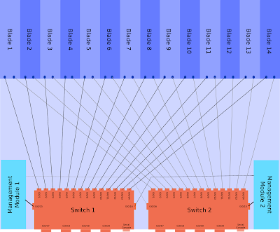
The CIGESM is a Cisco switch with 20 Gigabit Ethernet ports, these are:

  • 4 Physical ports on the back of the chassis.

  • 14 Ports connecting to the individual blades.

  • 2 Ports connecting to the internal Management Module for managing the switch via the chassis web interface.


Each of the blades is dual homed into the two CIGESM modules.

This architecture of a single blade center is shown below, click for larger version (warning 400kb image). This one assumes two management modules and two CIGESMs.


Management


The blade center itself is configured via a web interface that runs on the management module (MM). To access this initially you connect a copper cable directly into the MM port (has a picture of a network next to it), give your laptop an address in the 192.168.70.0/25 range and browse to 192.168.70.126. The default login is USERID/PASSW0RD (zero).

The CIGESM is a layer 2 switch and has a defined management interface, with the command "management" under the SVI. The Blade Center Management Module (MM) will configure the IP address on this interface. You can change it on the Cisco CLI but it will probably get set back by the MM at some point in future, so set it to the same on both MM and CLI!

CIGESM Management SVI


If you want to change the management interface VLAN then you'll need to do the following:

  1. If the IP is changing then update the network settings via the blade center web interface first.

  2. Create the layer 2 VLAN (for applying config to ports 15/16).

  3. Create the layer 3 SVI.

  4. Run the command "management" under the layer 3 SVI.

  5. Delete the old management interface.


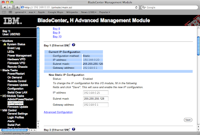
The web interface screen is shown below (names changed to protect the innocent), the network settings are under "I/O Module Tasks" -> "Configuration". Click for larger image:


An example of changing the management VLAN from 1 to 2, note the auto updates to Gi0/15&16 (explained later):

BC-Sw01(config-if)#int vlan 2
BC-Sw01(config-if)#management
Port Gi0/15 allowed vlan list updated to include vlan 2
Port Gi0/16 allowed vlan list updated to include vlan 2

BC-Sw01(config-if)#desc Management Interface
BC-Sw01(config-if)#ip address 192.168.0.25 255.255.255.128
BC-Sw01(config-if)#do show run interface vlan 2
interface Vlan2
description Management Interface
ip address 192.168.0.25 255.255.255.128
no ip route-cache
management
end


Internal Connections - Gi0/15 & Gi0/16


As shown in the architecture diagram above ports 15 & 16 are internal links to the management modules. These are used for communications between the MM and the switch, for instance if you click the "telnet" link within the MM web interface.

The management VLAN needs to be allowed over the internal link to the MM. Some parts of the configurations on these ports cannot be configured manually, such as access or native VLAN. These entries are set automatically when you specify an SVI for management.

If you try to reconfigure them on the CLI you'll see errors as below:
BC-Sw01(config)#int range gi0/15 - 16
BC-Sw01(config-if-range)#switchport access vlan 2
User prevented from modifing Ethernet port Gi0/15 access vlan

Command rejected: not allowed on this interface.User prevented from modifing Ethernet port Gi0/16 access vlan

Command rejected: not allowed on this interface.
BC-Sw01(config-if-range)#switchport trunk native vlan 2
User prevented from modifying Native VLAN on Port Gi0/15

Command rejected: not allowed on this interface.User prevented from modifying Native VLAN on Port Gi0/16

Command rejected: not allowed on this interface.
BC-Sw01(config-if-range)#switchport trunk allowed vlan 2
BC-Sw01(config-if-range)#


Read more...

Tuesday, 9 February 2010

VTP Version 3 and MSTP Walkthrough.

This article assumes you are familiar with MSTP and VTP.

The latest incarnation of VTP version 3 is now available on versions of IOS from 12.2(50)SE3 onwards for 3560, 3750 and 2960s.

It supports distribution of two databases:

  • VLAN Database.

  • MSTP Vlan-to-MSTI mapping database.


Other than support for extended ID VLANs the VLAN database functionality is the same as previous versions. The MST mappings were not previously supported however and you had to manually create them on every device before. They show which VLANs are part of which spanning tree (or MSTI).

Another VTP version 3 function is to define a primary server that will not accept updates from any other device. This is meant to stop VTP bombs. When a switch is configured as the primary server it broadcasts itself on the network, the other VTP devices then create an entry with the MAC of this primary server and refuse to accept updates from any other device.

Implementation


The outputs here are from a sup720 running SXI3 IOS.

Previously you only had to set the VTP server, version and spanning-tree mode globally with commands such as:

RTR01(config)#vtp mode server
RTR01(config)#vtp version 3
RTR01(config)#spanning-tree mode mst


This configures the VTP status as follows, VTP server but leaves VTP support for MSTP in transparent mode.

RTR01#sh vtp status
VTP Version : 3 (capable)
VTP version running : 3
VTP Domain Name : VTPDOMAIN
VTP Pruning Mode : Disabled (Operationally Disabled)
VTP Traps Generation : Enabled
Device ID : 0200.0000.000a

Feature VLAN:
--------------
VTP Operating Mode : Server
Number of existing VLANs : 5
Number of existing extended VLANs : 0
Configuration Revision : 0
Primary ID : 0000.0000.0000
Primary Description :
MD5 digest : 0x00 0x00 0x00 0x00 0x00 0x00 0x00 0x00
0x00 0x00 0x00 0x00 0x00 0x00 0x00 0x00


Feature MST:
--------------
VTP Operating Mode : Transparent


To set the server as the primary use the command “vtp primary vlan”, in enable mode not config mode.

RTR01#vtp primary vlan
This system is becoming primary server for feature vlan
No conflicting VTP3 devices found.
Do you want to continue? [confirm]

This then shows the log message:

000087: Feb 8 14:12:55.145: %SW_VLAN-SW1_SP-4-VTP_PRIMARY_SERVER_CHG: 0200.0000.000a has become the primary server for the VLAN VTP feature


At this point only the configured primary server can send VTP updates to the networks. Clients should ignore updates from any other device. The VTP status is now updated to show the VTP primary server.

RTR01#sh vtp status
[snip]

Feature VLAN:
--------------
VTP Operating Mode : Primary Server
Number of existing VLANs : 5
Number of existing extended VLANs : 0
Configuration Revision : 1
Primary ID : 0200.0000.000a
Primary Description : RTR01
MD5 digest : 0x87 0xBB 0xDB 0xEC 0xE5 0x9F 0x9C 0xCA
0x75 0xCE 0x4A 0x67 0xA7 0x67 0xBF 0xDA


The VLAN database is being synced but the MST mappings are not. To set up the device as the primary server for MST requires a few more steps:

RTR01(config)#vtp mode server mst
Setting device to VTP Server mode for MST.
RTR01(config)#^Z
RTR01#vtp primary mst
This system is becoming primary server for feature mst
No conflicting VTP3 devices found.
Do you want to continue? [confirm]
000091: Feb 8 14:15:20.932: %SW_VLAN-SW1_SP-4-VTP_PRIMARY_SERVER_CHG: 0200.0000.000a has become the primary server for the MST VTP feature


Now the VTP status is updated to show the primary server for both VLAN and MST.

RTR01#show vtp status
VTP Version : 3 (capable)
VTP version running : 3
VTP Domain Name : VTPDOMAIN
VTP Pruning Mode : Disabled (Operationally Disabled)
VTP Traps Generation : Enabled
Device ID : 0200.0000.000a

Feature VLAN:
--------------
VTP Operating Mode : Primary Server
Number of existing VLANs : 5
Number of existing extended VLANs : 0
Configuration Revision : 1
Primary ID : 0200.0000.000a
Primary Description : RTR01
MD5 digest : 0x87 0xBB 0xDB 0xEC 0xE5 0x9F 0x9C 0xCA
0x75 0xCE 0x4A 0x67 0xA7 0x67 0xBF 0xDA


Feature MST:
--------------
VTP Operating Mode : Primary Server
Configuration Revision : 1
Primary ID : 0200.0000.000a
Primary Description : RTR01
MD5 digest : 0xC6 0x62 0xA6 0x96 0x7E 0x98 0x14 0xCB
0x80 0xA1 0xA6 0x2D 0x60 0x39 0x49 0x39


Any devices on the network running VTP version 3 in the correct VTP domain should now sync VLANs and MST mappings.

EDIT:
Should really include the client configuration as that has also changed slightly, the old way was:

vtp domain XXXX
vtp mode client


To get the MST mappings you also need to run the command:

vtp mode client mst


And because changing the MST mapping later causes a total STP reconvergence you should configure all the MST mappings on day 1, but more about that later :-)


Read more...

Friday, 5 February 2010

Cisco Gotchas - 1800 Virtual Ports

This is a (very late) addition to the article here.

Cisco 6500 doesn't directly limit the number of spanning-tree instances. It has limits on the number of virtual ports per line card.


A virtual port is a VLAN being forwarded on a trunk. So if you have 10 VLANs and 5 active trunks with no pruning then you have 50 virtual ports.

A 6500 is limited to 1800 virtual ports per line-card (with caveats, see below!).

If you have a full 48-port linecard and use PVST then you can only create 37 VLANs before you hit the limit. If you intend to go over this then either manually prune some VLANs or upgrade.

Some of the SX IOS versions have removed the virtual port limit on the newer linecards (6500 and 6700 series), however the per-chassis limits still apply.

The per-chassis limits are shown here.

They are 10000 for RPVST+ and 13000 for PVST+, updated in IOS 12.2(33)SXI to be 12000/15000 respectively.


If you want to get extra lifetime out of older linecards then look into using MST as it drastically simplifies the forwarding. Unless you have a need for a different STP topology for every VLAN then it's a great idea.


Read more...

Cisco Gotchas - Max VLANs and STP Instances

Cisco switches have separate limitations on:

  • The number of VLANs that can exist in the database.

  • The number of Spanning-Tree Instances that can run.


Cisco kit tends to use per-VLAN spanning-tree in which case the two values will be the same.


To understand the problem and solution requires knowledge of the different types of spanning-tree available, this subject is huge but very briefly the types are:

  1. Standard 802.1D Spanning-Tree

  2. PVST, Per-VLAN Spanning-Tree (ISL trunking only)

  3. PVST+, Per-VLAN Spanning-Tree plus (compatible with 802.1q trunks)

  4. Rapid PVST - RSTP version of PVST+

  5. MST - Multiple Spanning Tree


The limitations are as follows on switches running PVST, PVST+ or Rapid-PVST:

  • 2950 SI: Maximum 64 STP instances, Maximum 128 VLANs.

  • 2950 EI: Maximum 64 STP instances, Maximum 250 VLANS.

  • 3550, 3560, 3750: Maximum 128 STP instances, Maximum 1005 VLANs.

  • 6500: Based on logical ports. Article here.


If you exceed the number of VLANs then you'll get an error like this:
SPANTREE_VLAN_SW-2-MAX_INSTANCE: Platform limit of 64 STP instances exceeded. No instance created for VLANxxx


Solutions


There are a couple of workarounds:

  • Delete some VLANs!

  • Manually prune VLANs off the trunk links and set the switch to VTP mode transparent so it doesn't know about the extra VLANs.

  • Use MST instead of PVST.


MST is my preferred option. Most networks will only require 2 or 4 Spanning-Tree topologies anyway so it is wasteful to have STP running in every VLAN.


Read more...

Cisco Gotchas - 16 Unique Standby Groups

HSRP is configured in standby groups, each one having an identifier value in the switch configuration.

The acceptable range of values is 0-255 and you can create as many as you want. Cisco don't recommended using more than 500 on a 6500 series or 64 on the 3550.

There are limitations on the number of unique ID values you can assign however.


Each instance is configured using the standby command:

interface FastEthernet 0/10
ip address 10.0.0.3 255.255.255.0
standby 10 ip 10.0.0.1
standby 10 preempt


The gotcha is that you can create as many groups as you want, but you can only use 16 different values for the ID.

This is hardware/software specific, but it's not clear what hardware it's specific to. The Cisco FAQ says it only affects PFC2, but their bug tracker doesn't mention the PFC and has a "fixed in" entry indicating that it's not an issue with newer software.

So feel free to create as many unique IDs as you like, but when adding the 17th check the logs to make sure it's actually working!

Or you could use VSS and get rid of HSRP entirely.

The Cisco FAQ for this issue on the 6500 is here.
There is a bug open on the Cisco tracker, CSCdx32496.


Read more...

Monday, 1 February 2010

Configure IOS by SNMP - Password Recovery

This is useful if you ever end up without a password for a router but you do know the SNMP read-write community values or usernames. It can save you the need to reboot a device and do a full password recovery, useful if the device is a thousand miles away and running some vital service.

You can load a configuration snippet into IOS from a TFTP server, triggered over SNMP.

The steps are:


Warning:

This can seriously b0rk your equipment and I accept no responsibility if it doesn't work for you. If your device is thousands of miles away, running critical services and you cannot login then your network has bigger issues than bodging the username on this one device! Don't do this unless you understand the possible consequences of blindly applying raw config to a Cisco device.


  1. Create a text file containing the config snippet.

  2. Run a TFTP server, on machine with IP 10.0.0.10 in this example.

  3. Set the value of iso.org.dod.internet.private.enterprises.cisco.lo cal.lsystem.hostConfigSet.10.0.0.10 to a string containing the filename from #2


The config snippet could be something like:

username cisco priv 15 password cisco


The command line for NET-SNMP tools snmpset is:

snmpset <router> <community> .iso.org.dod.internet.private.enterprises.cisco.local.lsystem.hostConfigSet.10.0.0.10 s <filename>


You can do a write mem via SNMP too if you want (but I wouldn't recommend it):

snmpset <router> <community> .iso.org.dod.internet.private.enterprises.cisco.local.lsystem.writeMem.0 i 1


If you can't login to a device and have absolutely no idea why not then it may not be as simple as adding a new local account. The specifics may be guessed at depending on how standardized your network is and you may be able to guess at the extra bits (heed the warning above), e.g.

no aaa new-model
username cisco priv 15 password cisco
line vty 0 15
login local
password cisco


Read more...

Saturday, 16 January 2010

VSS Introduction

VSS stands for Virtual Switching System and is a technology for use on 6500 series switches.

It works in a similar way to stackwise on the 3750s, you have two physical devices that end up with a single logical management plane.


In a large Cisco-style network you would have two core/distribution devices for redundancy. The network topology will typically need an active/standby topology. With Spanning-tree, only one uplink is forwarding for a given VLAN. To avoid unicast flooding the network should then have HSRP/VRRP and the IGP configured so that all traffic for that VLAN is routed via the same distribution (or core) switch.

Traffic is load balanced by alternating VLANs between the two distribution switches.

This topology is shown below for a single VLAN:


The basic VSS topology is shown below, the access device still has redundant uplinks but traffic flows over all links in etherchannels:


This topology it produces is similar to a network built around Nortel kit and the Split Multi-Link Trunking (SMLT) technology. The difference being that SMLT still has two separate management planes but VSS only has one.

There are a few benefits to this system:

Simplified Network Architecture.
  • Single logical device at the core/distribution layer.
  • Behaves as a single unit for management purposes.
  • No need to fudge STP, HSRP and IGP per VLAN.
  • No need of first hop redundancy protocols (FHRP).

Simpler Routing
  • Half as many IGP neighbors.
  • Half as many IGP routes.
  • No IGP load balancing/weighting required.


ISSU.
  • Software upgrades carried out without risky failovers and associated downtimes during convergence.
  • Easier to roll back.

Faster Convergence.
  • No STP convergence delays.
  • Loss of redundant switch does not change logical topology, avoiding convergence entirely.

Reduced function of Spanning-Tree.
  • No blocked ports to distribution/core from access layer.
  • Reduces greatly the chance of bridging loops.
  • Can use portfast trunk on access device uplinks.


The Cisco VSS Design Guide is well worth a read for more detailed information.


Read more...

3750 Stackwise Upgrades

Upgrading a Cisco switch is very easy:
  1. Copy IOS image to the flash drive on the switch.
  2. Point the boot statement at the new image.
  3. Reboot the switch.
The 3750 stack is made up of several physical devices with just a single logical management interface so Cisco has implemented the archive-sw command to make upgrading it easy. It doesn't quite work as well as it should and I wouldn't recommend using it. The method below is much easier and more reliable:

1. Copy IOS image to the flash drive on the switch
Use the same command as usual, but run it once for each switch in the stack. The flash drives are numbered flash1: flash2: flash3: etc.
copy tftp flash1:
copy tftp flash2:

Delete any old images or html files to clear space as necessary.

2. Point the boot statement at the new image
This can be done with a one liner (replace image.bin with whatever file you want to use):
boot system all flash:image.bin


3. Reboot the switch
The "reload" command will restart the entire stack.

So what's wrong with archive-sw?
The upgrade process is just the 3 simple steps above. Last time I used archive-sw I had about 45 minutes of instability while various individual processes restarted on the switch, routing went down but basic IP services stayed up so HSRP couldn't fail over and the network was unreachable until archive-sw had finished doing whatever it was doing. Maybe it was a bug in the archive-sw version I was using, maybe the config on that device triggered it, maybe it's just not very good.

Either way, I'm sticking to the old method of upgrades because it works and only causes an outage for the time it takes the switch to reboot (assuming it comes up again, which doesn't always happen with stacks!).


ISSU - In Service Software Upgrades
ISSU allows devices to be upgraded without outage. Unfortunately it is not available for 3750 stacks.
It may be possible to carry out the instructions above and then just reboot one switch at a time in the stack, if the old and new versions are similar enough then you might get away with it and the stack might re-form, allowing you to reboot the other switch while maintaining connectivity. Personally I wouldn't try it, if you want maximum uptime then you need two separate logical switches or to forget about upgrading them.


This method was worked out with our partners are Cacti Networks Ltd, network and security providers in the Ross-on-Wye area.

Read more...

Sunday, 6 September 2009

MPLS Lab Part 2

Follows on from part 1.

Now to get MP-BGP up and running on the MPLS lab. BGP-4 (as described in RFC 1771) can only carry IPv4 prefixes. RFC 2858 adds multiprotocol capability to BGP-4, which is needed to work with the vpnv4 routes that MPLS uses.


vpnv4?
In an MPLS network you may have customers with overlapping IP address space. In order to provide unique addressing, a vpnv4 prefix is used consisting of a Route Distinguisher (RD) followed by the IP prefix. The RD is 64 bits and typically in format AS:nn (or IP:nn). For example if you use an RD of 65001:1 and your IP prefix is 10.0.255.0/24 then the vpnv4 prefix is 65001:1:10.0.255.0/24.


The reason things are like this is because you have many customers sharing the same WAN, they are seperated by an MPLS VPN between their sites. This is done by using MP-BGP relationships as shown in the diagram below:


In this case I'm just setting up a single customer so the network looks like this:


Firstly I'll set up vanilla BGP-4 between PE1 and PE2, specifying to use the loopback interfaces for the peer relationships:


PE1#sh run | section bgp
router bgp 65001
no synchronization
bgp router-id 10.255.255.51
bgp log-neighbor-changes
neighbor 10.255.255.52 remote-as 65001
neighbor 10.255.255.52 update-source Loopback0
no auto-summary


PE1#show run | section bgp
router bgp 65001
no synchronization
bgp router-id 10.255.255.51
bgp log-neighbor-changes
neighbor 10.255.255.52 remote-as 65001
neighbor 10.255.255.52 update-source Loopback0
no auto-summary


When watching the debugs this gives:

*Mar 1 00:15:42.659: BGP: 10.255.255.52 passive open to 10.255.255.51
*Mar 1 00:15:42.659: BGP: 10.255.255.52 went from Active to Idle
*Mar 1 00:15:42.659: BGP: 10.255.255.52 went from Idle to Connect
*Mar 1 00:15:42.659: BGP: 10.255.255.52 rcv message type 1, length (excl. header) 26
*Mar 1 00:15:42.659: BGP: 10.255.255.52 rcv OPEN, version 4, holdtime 180 seconds
*Mar 1 00:15:42.659: BGP: 10.255.255.52 went from Connect to OpenSent
*Mar 1 00:15:42.659: BGP: 10.255.255.52 sending OPEN, version 4, my as: 65001, holdtime 180 seconds
*Mar 1 00:15:42.659: BGP: 10.255.255.52 rcv OPEN w/ OPTION parameter len: 16
*Mar 1 00:15:42.659: BGP: 10.255.255.52 rcvd OPEN w/ optional parameter type 2 (Capability) len 6
*Mar 1 00:15:42.659: BGP: 10.255.255.52 OPEN has CAP
PE1#ABILITY code: 1, length 4
*Mar 1 00:15:42.659: BGP: 10.255.255.52 OPEN has MP_EXT CAP for afi/safi: 1/1
*Mar 1 00:15:42.659: BGP: 10.255.255.52 rcvd OPEN w/ optional parameter type 2 (Capability) len 2
*Mar 1 00:15:42.659: BGP: 10.255.255.52 OPEN has CAPABILITY code: 128, length 0
*Mar 1 00:15:42.659: BGP: 10.255.255.52 OPEN has ROUTE-REFRESH capability(old) for all address-families
*Mar 1 00:15:42.659: BGP: 10.255.255.52 rcvd OPEN w/ optional parameter type 2 (Capability) len 2
*Mar 1 00:15:42.659: BGP: 10.255.255.52 OPEN has CAPABILITY code: 2, length 0
*Mar 1 00:15:42.659: BGP: 10.255.255.52 OPEN has ROUTE-REFRESH capability(new) for all address-families
BGP: 10.255.255.52 rcvd OPEN w/ remote AS 65001
*Mar 1 00:15:42.659: BGP: 10.255.255.52 went from OpenSent to OpenConfirm
*Mar 1 00:15:42.659: BGP: 10.255.255.52 send message type 1, length (incl. header) 45
*Mar 1 00:15:42.663: BGP: 10.255.255.52 went from OpenConfirm to Established
*Mar 1 00:15:42.663: %BGP-5-ADJCHANGE: neighbor 10.255.255.52 Up


The neighbor relationship is up

PE1#sh ip bgp nei
BGP neighbor is 10.255.255.52, remote AS 65001, internal link
BGP version 4, remote router ID 10.255.255.52
BGP state = Established, up for 00:01:42
Last read 00:00:41, last write 00:00:41, hold time is 180, keepalive interval is 60 seconds
Neighbor capabilities:
Route refresh: advertised and received(old & new)
Address family IPv4 Unicast: advertised and received


Two important bits are missing, the neighbor does not show capability "Address family VPNv4 Unicast" and the afi/safi values in the debug output don't show support for VPNv4.


*Mar 1 00:15:42.659: BGP: 10.255.255.52 OPEN has MP_EXT CAP for afi/safi: 1/1


The Address Family Identifier (AFI) and Subsequent Address Family Identifier (SAFI) values can be found on the IANA website: AFI and SAFI. An AFI of 1 is IPv4, SAFI of 1 is NRLI for unicast forwarding and SAFI of 128 is for labelled VPN forwarding.

To activate the vpnv4 support, a bit more configuration is required:


PE1#show run | section bgp
router bgp 65001
bgp router-id 10.255.255.51
bgp log-neighbor-changes
neighbor 10.255.255.52 remote-as 65001
neighbor 10.255.255.52 update-source Loopback0
!
address-family ipv4
neighbor 10.255.255.52 activate
no auto-summary
no synchronization
exit-address-family
!
address-family vpnv4
neighbor 10.255.255.52 activate
neighbor 10.255.255.52 send-community extended
exit-address-family


router bgp 65001
bgp router-id 10.255.255.52
bgp log-neighbor-changes
neighbor 10.255.255.51 remote-as 65001
neighbor 10.255.255.51 update-source Loopback0
!
address-family ipv4
neighbor 10.255.255.51 activate
no auto-summary
no synchronization
exit-address-family
!
address-family vpnv4
neighbor 10.255.255.51 activate
neighbor 10.255.255.51 send-community extended
exit-address-family


Now the debug line in question shows:

*Mar 1 00:21:31.183: BGP: 10.255.255.52 OPEN has MP_EXT CAP for afi/safi: 1/128

And the neighbor capabilities are listed as:

PE1#show ip bgp neigh
BGP neighbor is 10.255.255.52, remote AS 65001, internal link
BGP version 4, remote router ID 10.255.255.52
BGP state = Established, up for 00:00:54
Last read 00:00:54, last write 00:00:54, hold time is 180, keepalive interval is 60 seconds
Neighbor capabilities:
Route refresh: advertised and received(old & new)
Address family IPv4 Unicast: advertised and received
Address family VPNv4 Unicast: advertised and received


This gives us working MP-BGP between the two PE routers, but nothing is actually being advertised over BGP just yet because there are no redistribute or network statements.


Read more...

MPLS Lab Part 1

I'm currently studying MPLS for the CCIP qualification so will be putting up a series of articles on building a basic service-provider network to test various MPLS configurations.

The first article puts together a simple WAN running OSPF.


The network will look as below:


(These diagrams are all created using the excellent open source software dia)


The idea here is simply to get the provider part of the network up and running. The links are all using /30 masks and the core links are all using serial lines in this case (because I have plenty of WIC cards and no ethernet cards). It's actually a very simple OSPF network with everything in area 0 and MPLS enabled on all of the interfaces.

Because there are diverse routes across the network from PE-PE, there are two entries in the routing table, e.g. 10.255.255.52 (PE2) from PE1:

PE1#sh ip route 10.255.255.52
Routing entry for 10.255.255.52/32
Known via "ospf 1", distance 110, metric 129, type intra area
Last update from 10.0.0.6 on Serial0/1, 00:00:54 ago
Routing Descriptor Blocks:
10.0.0.6, from 10.255.255.52, 00:00:54 ago, via Serial0/1
Route metric is 129, traffic share count is 1
* 10.0.0.2, from 10.255.255.52, 00:00:54 ago, via Serial0/0
Route metric is 129, traffic share count is 1


The LFIB is populated on each router:

PE1#sh mpls forwarding-table
Local Outgoing Prefix Bytes tag Outgoing Next Hop
tag tag or VC or Tunnel Id switched interface
16 Pop tag 10.0.0.8/30 0 Se0/0 point2point
17 Pop tag 10.0.0.12/30 0 Se0/1 point2point
18 17 10.0.255.4/30 0 Se0/1 point2point
19 10.0.255.4/30 0 Se0/0 point2point
19 21 10.255.255.52/32 0 Se0/1 point2point
21 10.255.255.52/32 0 Se0/0 point2point
20 Pop tag 10.255.255.101/32 0 Se0/0 point2point
21 Pop tag 10.255.255.102/32 0 Se0/1 point2point

And the basic connectivity is working, PE1 can ping the loopback on PE2:

PE1#ping 10.255.255.52

Type escape sequence to abort.
Sending 5, 100-byte ICMP Echos to 10.255.255.52, timeout is 2 seconds:
!!!!!
Success rate is 100 percent (5/5), round-trip min/avg/max = 1/3/8 ms


This is almost CCNA level simplicity, which is good, KISS is a great principle to follow.


Question


So on this network, will the pings from PE1 to PE2 be load balanced across the two P routers?

Answer (highlight text to read):
No!
If you look at the PE1 route table, there are two routes to 10.255.255.52 and there are two MPLS labels which will allow load balancing of traffic, however the question was specifically about pings from PE1 to PE2.

So to find the answer you need to look at how the router decides which path to send traffic, which is done by CEF. The default CEF load balancing algorithm is per-destination (which is actually source & dest). As the source/dest are identical on all of the ICMP packets then they are not load balanced.

They would be load balanced if you turned on per-packet load balancing.


The relevant configuration bits are as follows (left out loopbacks for brevity):

PE1

interface Serial0/0
description To P1
ip address 10.0.0.1 255.255.255.252
mpls ip
!
interface Serial0/1
description To P2
ip address 10.0.0.5 255.255.255.252
mpls ip
!
router ospf 1
router-id 10.255.255.51
network 10.0.0.0 0.255.255.255 area 0


P1

interface Serial0/0
description To PE1
ip address 10.0.0.2 255.255.255.252
mpls ip
!
interface Serial0/1
description To PE2
ip address 10.0.0.9 255.255.255.252
mpls ip
!
router ospf 1
router-id 10.255.255.101
network 10.0.0.0 0.255.255.255 area 0


P2

interface Serial0/0
description To PE1
ip address 10.0.0.6 255.255.255.252
mpls ip
!
interface Serial0/1
description To PE2
ip address 10.0.0.13 255.255.255.252
mpls ip
!
router ospf 1
router-id 10.255.255.102
network 10.0.0.0 0.255.255.255 area 0


PE2

interface Serial0/0
description To P1
ip address 10.0.0.10 255.255.255.252
mpls ip
!
interface Serial0/1
description To P2
ip address 10.0.0.14 255.255.255.252
mpls ip
!
router ospf 1
router-id 10.255.255.52
network 10.0.0.0 0.255.255.255 area 0


Read more...

Monday, 22 June 2009

Locating a host

Something that often comes in handy is the ability to physically locate hosts on a large campus network from their IP address. This article assumes the device is correctly configured on the network.

The steps are:

  1. Find the devices MAC address.
  2. Locate the STP root bridge.
  3. On the root bridge follow the path to the MAC address.

1. Find the devices MAC address.


The MAC address can be found in the ARP cache of the hosts default gateway. To find the default gateway you need to run traceroute from any host on the same network (tracert on windows) which will give you something like the following:

matt@host:~$ traceroute 10.10.10.10
traceroute to 10.10.10.10 (10.10.10.10), 30 hops max, 60 byte packets
1 10.0.0.1 (10.0.0.1) 2.598 ms 2.875 ms 3.363 ms
2 10.10.10.10 (10.10.10.10) 3.908 ms 4.684 ms 4.363 ms

If the host is running a firewall then the last line may just show stars.

Connect (telnet/ssh) to the last hop before the device itself and check the ARP cache for the device. Remember that ARP entries time out after 4 hours of inactivity, the traceroute will refresh it.


Router# show ip arp 10.10.10.10

Protocol Address Age(min) Hardware Addr Type Interface
Internet 10.10.10.10 2 001e.1234.4321 ARPA VLAN 10


This output is from an MSFC card so the interface is the VLANs SVI. You may get a physical interface so check the CDP neighbors to ensure a switch is attached and not another router, if it is the a router then connect to it and keep tracing the address until you find a switch or VLAN interface. If you can't find it then check the NAT setup.

You now need to hop onto any switch associated with the interface shown above (VLAN 10 in this case). You may need some local knowledge or a bit more CDP investigation to find a suitable device. You may already be on it if it's a 6500 in native mode.

2. Locate the STP root bridge.
If you are working on a nicely designed network with combined routing/switching devices (e.g. 6500) then chances are good you're already logged onto the STP root bridge for that VLAN.

If not then find the VLAN you need by running
show mac-address-table address 001e.1234.4321


The commands needed here are:
show spanning-tree vlan 10
show cdp neighbors x/y

Check the spanning tree output, find the root port for that particular VLAN, check CDP neighbors for that port, connect to that device and repeat until you are sitting on the device that is the root bridge. It will either say clearly "this is the root bridge" or you'll be able to tell because the device MAC and root bridge MAC are identical.

3. On the root bridge follow the path to the MAC address.

In IOS/native mode use
show mac-address-table address 001e.1234.4321

In CatOS/hybrid mode use:
show cam dynamic 001e.1234.4321
or
show cam dynamic 00-1e-12-34-43-21
(the latter if it's really old CatOS and doesn't like new format MAC addresses)

This should give you a port, e.g. in IOS:

Router# show mac-address-table address 001e.1234.4321

vlan mac address type learn qos ports

------+----------------+--------+-----+---+--------------------------

10 001e.1234.4321 dynamic yes -- 2/6

or in CatOS the output looks like the following (if you get no output read the note at the end of this article):

coresw1> (enable) show cam dynamic 001e.1234.4321
* = Static Entry. + = Permanent Entry. # = System Entry. R = Router Entry.
X = Port Security Entry $ = Dot1x Security Entry

VLAN Dest MAC/Route Des [CoS] Destination Ports or VCs / [Protocol Type]
---- ------------------ ----- -------------------------------------------
10 001e.1234.4321 2/6 [ALL]


In this case the MAC is found on port 2/6. Assuming that isn't a copper port run "show cdp neighbors 2/6". Connect to that device and repeat this step until you get an answer pointing to a copper port.

You've now found the device!


Hopefully someone was thoughtful enough to either fill out the SNMP location field, the exec banner, the port description or to create a document telling you where on campus that switch is. It's now a simple matter to trace the cable and locate the device in question.


If you don't have any information beyond the switch name then it's time to start tracing cables and creating the documents yourself.


*note: CatOS will not show any output for "show cam dynamic 001e.1234.4321" if that MAC address is configured for port security on the local device as those addresses are not entered into the dynamic CAM table. In those cases you'll be able to find the port by running "show run | include 001e.1234.4321"

Read more...

SNMPv3 in CiscoWorks

A brief article on how I've got SNMPv3 working in older versions of CiscoWorks. This follows on from the SNMPv3 intro.

Ciscoworks only allows you to associate a single SNMP user account with each device. The same SNMP user account is used to poll the device and receive traps.

The new version of Device Fault Manager apparently has full SNMPv3 support. The older ones don't seem to, but they support polling devices with AuthPriv and you can use AuthNoPriv to send SNMPv3 traps to CiscoWorks.

So to get CiscoWorks to talk with an IOS device using SNMPv3 you need:
  • An AuthPriv account for SNMP polling.
  • That account configured in CiscoWorks in the devices properties.
  • Traps configured to use the same SNMP username, but with AuthNoPriv.

This may seem a bit unusual, defining an SNMPv3 user with a privacy key and then defining the same user without the key but it seems to work. The configuration I use is:

snmp-server group <group> v3 priv
snmp-server user <user> <group> v3 auth sha MYPASSWORD priv des PRIVPASS
snmp-server host <ip> traps version 3 auth <user>

With this configuration, you need to supply the encrypted password when polling the device, however when the device sends traps doesn't encrypt the packet contents (AuthNoPriv).


This article comes with a large dose of YMMV, it works on the version of CiscoWorks I've tested it with, it may not work on yours.

Read more...

SNMPv3

Quick article on SNMP version 3, focused on Cisco kit.

Previous versions of SNMP were configured using community strings and single-line commands in IOS.

SNMPv3 management is more like user/account management and the configuration does not appear in "show run" but is instead hidden in the private config. You access SNMPv3 configuration information via "show snmp x" commands.

SNMPv3 Communication.

There are three ways to configure SNMPv3 communication:
NoAuthNoPriv (called noauth in IOS) – username only authentication, packet sent cleartext.
AuthNoPriv (called auth in IOS) – HMAC authentication (SHA or MD5), packet sent cleartext.
AuthPriv (called priv in IOS) – HMAC authentication, encrypt entire packet.


SNMPv3 Groups.

Groups are configured as follows:
snmp-server group <groupname> v3 noauth|auth|priv [access X]


(access X is an ACL restricting hosts where accounts in the group can be accessed from).


SNMPv3 Users.

SNMP Users are configured as follows:
snmp-server user <user> <group> v3 auth <sha|md5> <pass> priv des <privpass> [access x]

Note: The password should be at least 8 letters long according to the RFC.


SNMPv3 Views.

These are used to control which MIBS the users can browse or which traps are allowed to be sent. There are three types:

Read views – Values you can look at by SNMP polling the device.
Write views – Values you can set via SNMP polling.
Notify views – Values that can be sent as SNMP traps.

I don't specifically use groups so the default settings are:

If you create a new group then it is given the read view "v1default".

If you create an SNMP trap configuration then the group associated with it has a notify view automatically generated by IOS. These views have names beginning with *tv.FFF


I've written a brief dit on getting older versions of CiscoWorks to support SNMPv3 here

Read more...