Monday, 22 June 2009

Locating a host

Something that often comes in handy is the ability to physically locate hosts on a large campus network from their IP address. This article assumes the device is correctly configured on the network.

The steps are:

  1. Find the devices MAC address.
  2. Locate the STP root bridge.
  3. On the root bridge follow the path to the MAC address.

1. Find the devices MAC address.


The MAC address can be found in the ARP cache of the hosts default gateway. To find the default gateway you need to run traceroute from any host on the same network (tracert on windows) which will give you something like the following:

matt@host:~$ traceroute 10.10.10.10
traceroute to 10.10.10.10 (10.10.10.10), 30 hops max, 60 byte packets
1 10.0.0.1 (10.0.0.1) 2.598 ms 2.875 ms 3.363 ms
2 10.10.10.10 (10.10.10.10) 3.908 ms 4.684 ms 4.363 ms

If the host is running a firewall then the last line may just show stars.

Connect (telnet/ssh) to the last hop before the device itself and check the ARP cache for the device. Remember that ARP entries time out after 4 hours of inactivity, the traceroute will refresh it.


Router# show ip arp 10.10.10.10

Protocol Address Age(min) Hardware Addr Type Interface
Internet 10.10.10.10 2 001e.1234.4321 ARPA VLAN 10


This output is from an MSFC card so the interface is the VLANs SVI. You may get a physical interface so check the CDP neighbors to ensure a switch is attached and not another router, if it is the a router then connect to it and keep tracing the address until you find a switch or VLAN interface. If you can't find it then check the NAT setup.

You now need to hop onto any switch associated with the interface shown above (VLAN 10 in this case). You may need some local knowledge or a bit more CDP investigation to find a suitable device. You may already be on it if it's a 6500 in native mode.

2. Locate the STP root bridge.
If you are working on a nicely designed network with combined routing/switching devices (e.g. 6500) then chances are good you're already logged onto the STP root bridge for that VLAN.

If not then find the VLAN you need by running
show mac-address-table address 001e.1234.4321


The commands needed here are:
show spanning-tree vlan 10
show cdp neighbors x/y

Check the spanning tree output, find the root port for that particular VLAN, check CDP neighbors for that port, connect to that device and repeat until you are sitting on the device that is the root bridge. It will either say clearly "this is the root bridge" or you'll be able to tell because the device MAC and root bridge MAC are identical.

3. On the root bridge follow the path to the MAC address.

In IOS/native mode use
show mac-address-table address 001e.1234.4321

In CatOS/hybrid mode use:
show cam dynamic 001e.1234.4321
or
show cam dynamic 00-1e-12-34-43-21
(the latter if it's really old CatOS and doesn't like new format MAC addresses)

This should give you a port, e.g. in IOS:

Router# show mac-address-table address 001e.1234.4321

vlan mac address type learn qos ports

------+----------------+--------+-----+---+--------------------------

10 001e.1234.4321 dynamic yes -- 2/6

or in CatOS the output looks like the following (if you get no output read the note at the end of this article):

coresw1> (enable) show cam dynamic 001e.1234.4321
* = Static Entry. + = Permanent Entry. # = System Entry. R = Router Entry.
X = Port Security Entry $ = Dot1x Security Entry

VLAN Dest MAC/Route Des [CoS] Destination Ports or VCs / [Protocol Type]
---- ------------------ ----- -------------------------------------------
10 001e.1234.4321 2/6 [ALL]


In this case the MAC is found on port 2/6. Assuming that isn't a copper port run "show cdp neighbors 2/6". Connect to that device and repeat this step until you get an answer pointing to a copper port.

You've now found the device!


Hopefully someone was thoughtful enough to either fill out the SNMP location field, the exec banner, the port description or to create a document telling you where on campus that switch is. It's now a simple matter to trace the cable and locate the device in question.


If you don't have any information beyond the switch name then it's time to start tracing cables and creating the documents yourself.


*note: CatOS will not show any output for "show cam dynamic 001e.1234.4321" if that MAC address is configured for port security on the local device as those addresses are not entered into the dynamic CAM table. In those cases you'll be able to find the port by running "show run | include 001e.1234.4321"

Read more...
SNMPv3 in CiscoWorks

A brief article on how I've got SNMPv3 working in older versions of CiscoWorks. This follows on from the SNMPv3 intro.

Ciscoworks only allows you to associate a single SNMP user account with each device. The same SNMP user account is used to poll the device and receive traps.

The new version of Device Fault Manager apparently has full SNMPv3 support. The older ones don't seem to, but they support polling devices with AuthPriv and you can use AuthNoPriv to send SNMPv3 traps to CiscoWorks.

So to get CiscoWorks to talk with an IOS device using SNMPv3 you need:
  • An AuthPriv account for SNMP polling.
  • That account configured in CiscoWorks in the devices properties.
  • Traps configured to use the same SNMP username, but with AuthNoPriv.

This may seem a bit unusual, defining an SNMPv3 user with a privacy key and then defining the same user without the key but it seems to work. The configuration I use is:

snmp-server group <group> v3 priv
snmp-server user <user> <group> v3 auth sha MYPASSWORD priv des PRIVPASS
snmp-server host <ip> traps version 3 auth <user>

With this configuration, you need to supply the encrypted password when polling the device, however when the device sends traps doesn't encrypt the packet contents (AuthNoPriv).


This article comes with a large dose of YMMV, it works on the version of CiscoWorks I've tested it with, it may not work on yours.

Read more...

SNMPv3

Quick article on SNMP version 3, focused on Cisco kit.

Previous versions of SNMP were configured using community strings and single-line commands in IOS.

SNMPv3 management is more like user/account management and the configuration does not appear in "show run" but is instead hidden in the private config. You access SNMPv3 configuration information via "show snmp x" commands.

SNMPv3 Communication.

There are three ways to configure SNMPv3 communication:
NoAuthNoPriv (called noauth in IOS) – username only authentication, packet sent cleartext.
AuthNoPriv (called auth in IOS) – HMAC authentication (SHA or MD5), packet sent cleartext.
AuthPriv (called priv in IOS) – HMAC authentication, encrypt entire packet.


SNMPv3 Groups.

Groups are configured as follows:
snmp-server group <groupname> v3 noauth|auth|priv [access X]


(access X is an ACL restricting hosts where accounts in the group can be accessed from).


SNMPv3 Users.

SNMP Users are configured as follows:
snmp-server user <user> <group> v3 auth <sha|md5> <pass> priv des <privpass> [access x]

Note: The password should be at least 8 letters long according to the RFC.


SNMPv3 Views.

These are used to control which MIBS the users can browse or which traps are allowed to be sent. There are three types:

Read views – Values you can look at by SNMP polling the device.
Write views – Values you can set via SNMP polling.
Notify views – Values that can be sent as SNMP traps.

I don't specifically use groups so the default settings are:

If you create a new group then it is given the read view "v1default".

If you create an SNMP trap configuration then the group associated with it has a notify view automatically generated by IOS. These views have names beginning with *tv.FFF


I've written a brief dit on getting older versions of CiscoWorks to support SNMPv3 here

Read more...

Monday, 8 June 2009

Checkpoint to Cisco VPNs #2

This is part 2 of the article started here. I'll be creating traditional mode VPN rules, because they are less abstracted than VPN communities and a bit easier to understand (in my opinion). There are some complications*.

To follow a similar methodology to that used on the Cisco router, the steps are as follows:
  1. Define the ISAKMP (phase 1) policy.
  2. Define the IPsec (phase 2) policy.
  3. Create the firewall rule specifying traffic to pass over the VPN.
  4. Define the encryption domains.

Checkpoint doesn't really have a concept of applying the crypto map to an interface as with Cisco. The Cisco concept of a crypto map is close to the encryption domains on Checkpoint.


1. Define the ISAKMP (phase 1) policy.

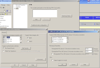
In Checkpoint the ISAKMP configuration is applied to an "interoperable device" object created for the Cisco VPN gateway. Edit your interoperable device and select "traditional mode configuration" on the "VPN" page to open the ISAKMP properties as shown here:

You configure encryption and integrity, specify to use a pre-shared secret (although you won't be able to enter one just yet) and in the "Advanced" options you can specify DH and lifetimes.

Be careful as the Cisco and Checkpoint default lifetimes do not match.

In practice, ISAKMP can negotiate new keys when the old ones are due to expire but best to make them match anyway to keep things tidy.


2. Define the IPsec (phase 2) policy.
3. Create the firewall rule specifying traffic to pass over the VPN.

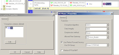
IPSec policy is defined under the actual firewall rule which also specifies the interesting traffic. Create a rule allowing the VPN traffic through the firewall (using pre-NAT addresses) and set the action to be "Encrypt"*. Double click on "Encrypt" and you can edit the IPSec settings for the connection.

In this case we're using 3DES/MD5, DH group 2 and specifying which interoperable device the VPN is talking to.

The traffic being allowed is between 10.0.0.0/24 (local) and 172.16.0.0/24 (remote) in either direction and Any protocol.


4. Define the encryption domains.

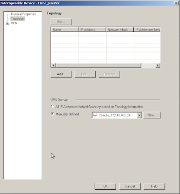
The encryption domains on Checkpoint are defined as properties of the gateway objects. Edit the interoperable device and open the "Toplogy" page, you can either manually set the topology or use another object to represent the encryption domain.

Here I am using the Remote_172.16.0.0_24 network object to define the Cisco end of the VPN encryption domain.

If you do destination NAT then the encryption domain is the post-NAT address as opposed to the firewall rules which must contain the pre-NAT address.


So that's the remote encryption domain defined, the local encryption domain is specified in the Checkpoint gateway object in the same way. The best way to do this is with a group, so that you can easily add further subnets in future if needed.


There is just one thing missing from the above, the shared key. This is actually defined on your local Checkpoint object rather than the remote peer's object. The reason I put this last is that the peer name won't show up until you've configured the interoperable device properties.

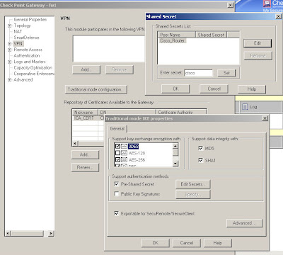
Edit your own Checkpoint enforcement module and open the VPN "Traditional mode configuration", then use the "Edit Secrets" button and you should see an entry for each of your VPN peers that have the "Pre-Shared Secret" box ticked.

Simply select the peer and enter the secret, "cisco" in this case.


Now having said all of the above, I will also say that making these systems interact nicely is a tricky business and you may find that it doesn't work even if you've followed these instructions to the letter.

Part 3 of this series of articles will include some troubleshooting methods to try and help fix any problems.


* Note: Checkpoint firewall policies are either in traditional VPN mode or simplified VPN mode which uses communities rather than the rules shown above.

If you don't have the "Encrypt" option in the Action column or if you have a "VPN" column then you're using a simplified VPN policy and cannot create traditional mode VPNs. Unfortunately you cannot convert a policy from simplified mode to traditional so your options are either to create a new policy from scratch, specifying "traditional" when you create it, or to use VPN communities instead.

Read more...