| OSPF Interface Cost | |||||
| Ref Speed | Ref BW Value | 10mbit link | 100mbit link | 1gbit link | 10gbit link |
| 100mbit | 100 | 10 | 1 | 1 | 1 |
| 1gbit | 1000 | 100 | 10 | 1 | 1 |
| 10gbit | 10000 | 1000 | 100 | 10 | 1 |
| 20gbit | 20000 | 2000 | 200 | 20 | 2 |
| 100gbit | 100000 | 10000 | 1000 | 100 | 10 |
Read more...
Yet another networking blog
| OSPF Interface Cost | |||||
| Ref Speed | Ref BW Value | 10mbit link | 100mbit link | 1gbit link | 10gbit link |
| 100mbit | 100 | 10 | 1 | 1 | 1 |
| 1gbit | 1000 | 100 | 10 | 1 | 1 |
| 10gbit | 10000 | 1000 | 100 | 10 | 1 |
| 20gbit | 20000 | 2000 | 200 | 20 | 2 |
| 100gbit | 100000 | 10000 | 1000 | 100 | 10 |


Edit src/vboxdrv*/Makefile and uncomment the line: # VBOX_USE_INSERT_PAGE = 1

Then run the script /etc/init.d/vboxdrv setup
Edit /usr/src/vboxdrv*/Makefile and uncomment the line: # VBOX_USE_INSERT_PAGE = 1

cd /usr/src
ln -s vboxdrv-2.1.4 vboxdrv
ln -s vboxnetflt-2.1.4 vboxnetflt
cd /usr/lib/virtualbox
ln -s /usr/src .

Run /etc/init.d/virtualbox-ose setup
setup()
{
    stop

    [snip]

    begin_msg "Recompiling VirtualBox kernel module"
    if ! $BUILDVBOXDRV \
        --save-module-symvers /tmp/vboxdrv-Module.symvers \
        --no-print-directory install > $LOG 2>&1; then
        failure "Look at $LOG to find out what went wrong"
    fi
    if ! $BUILDVBOXNETFLT \
        --use-module-symvers /tmp/vboxdrv-Module.symvers \
        --no-print-directory install >> $LOG 2>&1; then
        failure "Look at $LOG to find out what went wrong"
    fi
    rm -f /etc/vbox/module_not_compiled
    succ_msg
    start
}
Creating the Certificate Authority First, create an initial working environment, for example within your home directory by issuing the following command from a terminal prompt: cd && mkdir -p myCA/signedcerts && mkdir myCA/private && cd myCA The above command will place you in a newly-created subdirectory of your home directory named myCA, and within this subdirectory, you should have two additional subdirectories named signedcerts and private. Within this initial working environment, the significance of the subdirectories, and their contents is as follows: ~/myCA : contains CA certificate, certificates database, generated certificates, keys, and requests ~/myCA/signedcerts : contains copies of each signed certificate ~/myCA/private : contains the private key Next, create an initial certificate database in the ~/myCA subdirectory with the following command at a terminal prompt: echo '01' > serial && touch index.txt Now create an initial caconfig.cnf file suitable for the creation of CA certificates. Using your favorite editor, edit the file ~/myCA/caconfig.cnf, and insert the following content into the file: sudo nano ~/myCA/caconfig.cnf # My sample caconfig.cnf file. # # Default configuration to use when one is not provided on the command line. # [ ca ] default_ca = local_ca # # # Default location of directories and files needed to generate certificates. # [ local_ca ] dir = /home//myCA certificate = $dir/cacert.pem database = $dir/index.txt new_certs_dir = $dir/signedcerts private_key = $dir/private/cakey.pem serial = $dir/serial # # # Default expiration and encryption policies for certificates. # default_crl_days = 365 default_days = 1825 default_md = md5 # policy = local_ca_policy x509_extensions = local_ca_extensions # # # Default policy to use when generating server certificates. The following # fields must be defined in the server certificate. # [ local_ca_policy ] commonName = supplied stateOrProvinceName = supplied countryName = supplied emailAddress = supplied organizationName = supplied organizationalUnitName = supplied # # # x509 extensions to use when generating server certificates. # [ local_ca_extensions ] subjectAltName = DNS:alt.tradeshowhell.com basicConstraints = CA:false nsCertType = server # # # The default root certificate generation policy. # [ req ] default_bits = 2048 default_keyfile = /home/ /myCA/private/cakey.pem default_md = md5 # prompt = no distinguished_name = root_ca_distinguished_name x509_extensions = root_ca_extensions # # # Root Certificate Authority distinguished name. Change these fields to match # your local environment! # [ root_ca_distinguished_name ] commonName = MyOwn Root Certificate Authority stateOrProvinceName = NC countryName = US emailAddress = root@tradeshowhell.com organizationName = Trade Show Hell organizationalUnitName = IT Department # [ root_ca_extensions ] basicConstraints = CA:true IMPORTANT: Make sure to adjust the obvious site-specific details in the file, such as the two instances of /home/ / under [ local_ca ] and [ req ]. Also change commonName, stateOrProvinceName countryName etc under [ root_ca_distinguished_name ] to personalize for your environment. For more information on the directives contained within this configuration file, use the man config command. When you've edited the file to match your environment, save the file as ~/myCA/caconfig.cnf. Next, you need to generate the Certificate Authority Root Certificate and Key, by issuing a few commands. First, do this: export OPENSSL_CONF=~/myCA/caconfig.cnf The previous command sets an environment variable, OPENSSL_CONF, which forces the openssl tool to look for a configuration file in an alternative location (in this case, ~/myCA/caconfig.cnf). Now, generate the CA certificate and key with the following command: openssl req -x509 -newkey rsa:2048 -out cacert.pem -outform PEM -days 1825 You should be prompted for a passphrase, and see output similar to this: Generating a 2048 bit RSA private key .................................+++ .................................................................................................+++ writing new private key to '/home/bshumate/myCA/private/cakey.pem' Enter PEM pass phrase: Verifying - Enter PEM pass phrase: ----- Do not forget the passphrase used with the command above! You'll need it every time you want to generate and sign a new server or client certificate! The above process will create a self-signed certificate using PEM format and RSA public/private key encryption. The certificate will be valid for 1825 days. The location, and purpose of the resultant files is as follows: ~/myCA/cacert.pem : CA public certificate ~/myCA/private/cakey.pem : CA private key Optional Step Strip the certificate from all its text to keep only the -CERTIFICATE- section to create a crt openssl x509 -in cacert.pem -out cacert.crt Creating a Self-Signed Server Certificate Now that you have a Certificate Authority configured, you may use it to sign self-signed certificates. Prior to beginning the steps below, you may wish to encrypt the certificate's private key with a passphrase. The advantages of encrypting the key with a passphrase include protection of the certificate in the event it is stolen. The certificate cannot be used with SSL-enabled applications without entering the passphrase every time the SSL-enabled application is started. This condition, while being most secure, can present a problem: If the server must be started in an unattended manner as in the case of a computer restart, then no one will be available to enter the passphrase, and subsequently the server will not start. One way to eliminate this condition involves a trade-off in security: The key may be decrypted, to remove the passphrase necessity; thus SSL-enabled applications will start automatically, without a need for you to enter a passphrase. To actually generate a self-signed certificate for use with an SSL application, follow this process: Create the server configuration file, by editing ~/myCA/exampleserver.cnf with your favorite text editor. Add this example content: # # exampleserver.cnf # [ req ] prompt = no distinguished_name = server_distinguished_name [ server_distinguished_name ] commonName = tradeshowhell.com stateOrProvinceName = NC countryName = US emailAddress = root@tradeshowhell.com organizationName = My Organization Name organizationalUnitName = Subunit of My Large Organization Be sure to change the values under server_distinguished_name especially the commonName value. The commonName value must match the host name, or CNAME for the host you wish to use the key for. If the commonName does not match the intended hostname, then host / certificate mismatch errors will appear in the client applications of clients attempting to access the server. Once you've edited the file appropriately, save it as ~/myCA/exampleserver.cnf. Generate the server certificate, and key with the following commands: export OPENSSL_CONF=~/myCA/exampleserver.cnf The previous command sets an environment variable OPENSSL_CONF which forces the openssl tool to look for a configuration file in an alternative location (in this case, ~/myCA/exampleserver.cnf). Now generate the certificate, and key: openssl req -newkey rsa:1024 -keyout tempkey.pem -keyform PEM -out tempreq.pem -outform PEM You should be prompted for a passphrase, and see output similar to this: Generating a 1024 bit RSA private key ...++++++ ...............++++++ writing new private key to 'tempkey.pem' Enter PEM pass phrase: Verifying - Enter PEM pass phrase: ----- Don't forget the passphrase! Next, you may translate the temporary private key into an unencrypted key by using the following command: openssl rsa < tempkey.pem > server_key.pem You should be prompted for the passphrase used above, and see the following output: Enter pass phrase: writing RSA key If you wish to leave the key encrypted with a passphrase, simply rename the temporary key using the following command, instead of following the step above: mv tempkey.pem server_key.pem Remember: If you use a server key encrypted with a passphrase, the passphrase will have to be entered each time the server application using the encrypted key is started. This means the server application will not start unless someone, or something enters the key. Now you need to sign the server certificate with the Certificate Authority (CA) key using these commands: export OPENSSL_CONF=~/myCA/caconfig.cnf The previous command modifies the environment variable OPENSSL_CONF which forces the openssl tool to look for a configuration file in an alternative location (in this case, ~/myCA/caconfig.cnf to switch back to the CA configuration). Then sign the certificate as follows: openssl ca -in tempreq.pem -out server_crt.pem You will be prompted for the passphrase of the CA key as created in the Certificate Authority setup from above. Enter this passphrase at the prompt, and you will then be prompted to confirm the information in the exampleserver.cnf, and finally asked to confirm signing the certificate. Output should be similar to this: Using configuration from /home/bshumate/myCA/caconfig.cnf Enter pass phrase for /home/bshumate/myCA/private/cakey.pem: Check that the request matches the signature Signature ok The Subject's Distinguished Name is as follows commonName :PRINTABLE:'tradeshowhell.com' stateOrProvinceName :PRINTABLE:'NC' countryName :PRINTABLE:'US' emailAddress :IA5STRING:'root@tradeshowhell.com' organizationName :PRINTABLE:'Trade Show Hell' organizationalUnitName:PRINTABLE:'Black Ops' Certificate is to be certified until Jan 4 21:50:08 2011 GMT (1825 days) Sign the certificate? [y/n]:y 1 out of 1 certificate requests certified, commit? [y/n]y Write out database with 1 new entries Data Base Updated Remove the temporary certificate, and key files with the following command: rm -f tempkey.pem && rm -f tempreq.pem Congratulations! You now have a self-signed server application certificate, and key pair: server_crt.pem : Server application certificate file server_key.pem : Server application key file
[ local_ca_policy ]
commonName              = supplied
stateOrProvinceName     = optional
countryName             = optional
emailAddress            = optional
organizationName        = optional
organizationalUnitName  = optional
openssl req -x509 -newkey rsa:1024 -out cacert.pem -outform PEM -days 1825
openssl x509 -text -in <CERT>
openssl req -text -noout -in <CSR>
openssl req -text -noout -in <CSR> -verify
openssl ca -in <CSR> -out <SIGNED-CERT>
tcpdump -s1700 -w output.cap -ni <interface> host <IP-addr>
fw monitor -e 'accept src=<src-ip> or dst=<dst-ip>;'

CE1#show ip route

    172.16.0.0/24 is subnetted, 2 subnets
C       172.16.1.0 is directly connected, FastEthernet0/1
O IA    172.16.2.0 [110/20] via 10.0.255.2, 00:01:15, FastEthernet0/0
    10.0.0.0/8 is variably subnetted, 3 subnets, 2 masks
O E2    10.254.254.52/32 [110/10] via 10.0.255.2, 00:01:10, FastEthernet0/0
O IA    10.0.255.4/30 [110/20] via 10.0.255.2, 00:01:15, FastEthernet0/0
C       10.0.255.0/30 is directly connected, FastEthernet0/0
CE1#show run int s0/0
Building configuration...

Current configuration : 142 bytes
!
interface Serial0/0
description Backup Link to Site 2
ip address 192.168.255.1 255.255.255.0
ip ospf cost 30000
clock rate 2000000

CE1#show ip route
[snip]
    172.16.0.0/24 is subnetted, 2 subnets
C       172.16.1.0 is directly connected, FastEthernet0/1
O       172.16.2.0 [110/30010] via 192.168.255.2, 00:00:51, Serial0/0
    10.0.0.0/8 is variably subnetted, 4 subnets, 2 masks
O E2    10.254.254.51/32 [110/10] via 192.168.255.2, 00:00:51, Serial0/0
O E2    10.254.254.52/32 [110/10] via 10.0.255.2, 00:00:51, FastEthernet0/0
O       10.0.255.4/30 [110/30010] via 192.168.255.2, 00:00:51, Serial0/0
C       10.0.255.0/30 is directly connected, FastEthernet0/0
C    192.168.255.0/24 is directly connected, Serial0/0
PE1#show run int loop1
Building configuration...

Current configuration : 96 bytes
!
interface Loopback1
 ip vrf forwarding VPN_ONE
 ip address 10.254.254.51 255.255.255.255
end
!
PE1#show run | section ospf
router ospf 100 vrf VPN_ONE
 router-id 10.254.254.51
 area 0 sham-link 10.254.254.51 10.254.254.52 cost 10
PE1#show ip ospf 100 nei

Neighbor ID     Pri   State           Dead Time   Address         Interface
10.254.254.52     0   FULL/  -           -        10.254.254.52   OSPF_SL0
172.16.1.1        1   FULL/DR         00:00:34    10.0.255.1      FastEthernet0/0

PE1#show ip ospf 100 int
OSPF_SL0 is up, line protocol is up
  Internet Address 0.0.0.0/0, Area 0
  Process ID 100, Router ID 10.254.254.51, Network Type SHAM_LINK, Cost: 10
CE1#show ip route
[snip]
     172.16.0.0/24 is subnetted, 2 subnets
C       172.16.1.0 is directly connected, FastEthernet0/1
O       172.16.2.0 [110/40] via 10.0.255.2, 00:07:56, FastEthernet0/0
     10.0.0.0/8 is variably subnetted, 4 subnets, 2 masks
O E2    10.254.254.51/32 [110/10] via 10.0.255.2, 00:07:56, FastEthernet0/0
O E2    10.254.254.52/32 [110/10] via 10.0.255.2, 00:07:56, FastEthernet0/0
O       10.0.255.4/30 [110/30] via 10.0.255.2, 00:07:56, FastEthernet0/0
C       10.0.255.0/30 is directly connected, FastEthernet0/0
C    192.168.255.0/24 is directly connected, Serial0/0


PE2#show ip bgp vpnv4 vrf VPN_ONE 172.16.1.0
BGP routing table entry for 1:1:172.16.1.0/24, version 32
Paths: (1 available, best #1, table VPN_ONE)
Flag: 0x820
  Not advertised to any peer
  Local
    10.255.255.51 (metric 129) from 10.255.255.51 (10.255.255.51)
      Origin incomplete, metric 10, localpref 100, valid, internal, best
      Extended Community: RT:1:1 OSPF DOMAIN ID:0x0005:0x000000640200
        OSPF RT:0.0.0.0:3:0 OSPF ROUTER ID:10.254.254.51:0
      mpls labels in/out 23/26
CE2#show ip ospf database summary 172.16.1.0

            OSPF Router with ID (172.16.2.1) (Process ID 100)

  Summary Net Link States (Area 0)

  Routing Bit Set on this LSA
  LS age: 618
  Options: (No TOS-capability, DC, Downward)
  LS Type: Summary Links(Network)
  Link State ID: 172.16.1.0 (summary Network Number)
  Advertising Router: 10.254.254.52
  LS Seq Number: 80000001
  Checksum: 0x5167
  Length: 28
  Network Mask: /24
 TOS: 0  Metric: 10
PE1

ip vrf VPN_ONE
 rd 1:1
 route-target export 1:1
 route-target import 1:1

interface Loopback1
 ip vrf forwarding VPN_ONE
 ip address 10.254.254.51 255.255.255.255

interface FastEthernet0/0
 description To CE1
 ip vrf forwarding VPN_ONE
 ip address 10.0.255.2 255.255.255.252

router ospf 100 vrf VPN_ONE
 router-id 10.254.254.51
 redistribute bgp 65001 metric 10 subnets
 network 10.0.255.2 0.0.0.0 area 0

router bgp 65001
[snip - see previous articles for full BGP config]
 !
 address-family ipv4 vrf VPN_ONE
  redistribute connected
  redistribute ospf 100 vrf VPN_ONE metric 10 match internal external 1 external 2
 exit-address-family


CE1
interface FastEthernet0/0
 description To PE1
 ip address 10.0.255.1 255.255.255.252

interface FastEthernet0/1
 ip address 172.16.1.1 255.255.255.0

router ospf 100
 log-adjacency-changes
 network 10.0.255.1 0.0.0.0 area 0
 network 172.16.1.1 0.0.0.0 area 101
ip vrf VPN_ONE
rd 1:1
route-target export 1:1
route-target import 1:1
PE1#show run int fastEthernet 0/0
Building configuration...

Current configuration : 153 bytes
!
interface FastEthernet0/0
description To CE1
ip vrf forwarding VPN_ONE
ip address 10.0.255.2 255.255.255.252
end

PE2#show run int fastEthernet 0/0
Building configuration...

Current configuration : 153 bytes
!
interface FastEthernet0/0
description To CE2
ip vrf forwarding VPN_ONE
ip address 10.0.255.5 255.255.255.252
end
CE1#show ip route
[snip]
S*   0.0.0.0/0 [1/0] via 10.0.255.2


CE1 to PE1
Type escape sequence to abort.
Sending 5, 100-byte ICMP Echos to 10.0.255.2, timeout is 2 seconds:
!!!!!
Success rate is 100 percent (5/5), round-trip min/avg/max = 1/5/8 ms

CE1 to CE2
Type escape sequence to abort.
Sending 5, 100-byte ICMP Echos to 10.0.255.6, timeout is 2 seconds:
U.U.U
Success rate is 0 percent (0/5)
CE1#ping 10.0.0.9

CE1 to P1
Type escape sequence to abort.
Sending 5, 100-byte ICMP Echos to 10.0.0.9, timeout is 2 seconds:
U.U.U
Success rate is 0 percent (0/5)
PE1#config term
Enter configuration commands, one per line.  End with CNTL/Z.
PE1(config)#router bgp 65001
PE1(config-router)#address-family ipv4 vrf VPN_ONE
PE1(config-router-af)#redistribute connected
PE1#show ip bgp vpnv4 vrf VPN_ONE
BGP table version is 17, local router ID is 10.255.255.51
Status codes: s suppressed, d damped, h history, * valid, > best, i - internal,
             r RIB-failure, S Stale
Origin codes: i - IGP, e - EGP, ? - incomplete

  Network          Next Hop            Metric LocPrf Weight Path
Route Distinguisher: 1:1 (default for vrf VPN_ONE)
*> 10.0.255.0/30    0.0.0.0                  0         32768 ?
*>i10.0.255.4/30    10.255.255.52            0    100      0 ?
CE1#ping 10.0.255.6

Type escape sequence to abort.
Sending 5, 100-byte ICMP Echos to 10.0.255.6, timeout is 2 seconds:
!!!!!
Success rate is 100 percent (5/5), round-trip min/avg/max = 8/11/16 ms
hostname PE1
!
ip vrf VPN_ONE
rd 1:1
route-target export 1:1
route-target import 1:1
!
interface Loopback0
ip address 10.255.255.51 255.255.255.255
!
interface FastEthernet0/0
description To CE1
ip vrf forwarding VPN_ONE
ip address 10.0.255.2 255.255.255.252
!
interface Serial0/0
description To P1
ip address 10.0.0.1 255.255.255.252
mpls ip
!
interface Serial0/1
description To P2
ip address 10.0.0.5 255.255.255.252
mpls ip
!
router ospf 1
router-id 10.255.255.51
network 10.0.0.0 0.255.255.255 area 0
!
router bgp 65001
bgp router-id 10.255.255.51
neighbor 10.255.255.52 remote-as 65001
neighbor 10.255.255.52 update-source Loopback0
!
address-family ipv4
 neighbor 10.255.255.52 activate
exit-address-family
!
address-family vpnv4
 neighbor 10.255.255.52 activate
 neighbor 10.255.255.52 send-community extended
exit-address-family
!
address-family ipv4 vrf VPN_ONE
 redistribute connected
exit-address-family
PE1show ip route
Codes: C - connected, S - static, R - RIP, M - mobile, B - BGP
       D - EIGRP, EX - EIGRP external, O - OSPF, IA - OSPF inter area
       N1 - OSPF NSSA external type 1, N2 - OSPF NSSA external type 2
       E1 - OSPF external type 1, E2 - OSPF external type 2
       i - IS-IS, su - IS-IS summary, L1 - IS-IS level-1, L2 - IS-IS level-2
       ia - IS-IS inter area, * - candidate default, U - per-user static route
       o - ODR, P - periodic downloaded static route

Gateway of last resort is not set

     10.0.0.0/8 is variably subnetted, 8 subnets, 2 masks
O       10.0.0.8/30 [110/128] via 10.0.0.2, 00:26:46, Serial0/0
O       10.0.0.12/30 [110/128] via 10.0.0.6, 00:26:46, Serial0/1
C       10.0.0.0/30 is directly connected, Serial0/0
C       10.0.0.4/30 is directly connected, Serial0/1
C       10.255.255.51/32 is directly connected, Loopback0
O       10.255.255.52/32 [110/129] via 10.0.0.6, 00:26:46, Serial0/1
                         [110/129] via 10.0.0.2, 00:26:46, Serial0/0
O       10.255.255.102/32 [110/65] via 10.0.0.6, 00:26:46, Serial0/1
O       10.255.255.101/32 [110/65] via 10.0.0.2, 00:26:46, Serial0/0
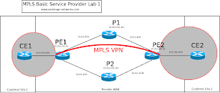
PE1ping 10.0.255.6

Type escape sequence to abort.
Sending 5, 100-byte ICMP Echos to 10.0.255.6, timeout is 2 seconds:
.....
Success rate is 0 percent (0/5)
PE1#ping vrf VPN_ONE ip 10.0.255.6

Type escape sequence to abort.
Sending 5, 100-byte ICMP Echos to 10.0.255.6, timeout is 2 seconds:
!!!!!
Success rate is 100 percent (5/5), round-trip min/avg/max = 4/6/8 ms


PE1#sh run | section bgp
router bgp 65001
 no synchronization
 bgp router-id 10.255.255.51
 bgp log-neighbor-changes
 neighbor 10.255.255.52 remote-as 65001
 neighbor 10.255.255.52 update-source Loopback0
 no auto-summary


PE1#show run | section bgp
router bgp 65001
 no synchronization
 bgp router-id 10.255.255.51
 bgp log-neighbor-changes
 neighbor 10.255.255.52 remote-as 65001
 neighbor 10.255.255.52 update-source Loopback0
 no auto-summary
*Mar  1 00:15:42.659: BGP: 10.255.255.52 passive open to 10.255.255.51
*Mar  1 00:15:42.659: BGP: 10.255.255.52 went from Active to Idle
*Mar  1 00:15:42.659: BGP: 10.255.255.52 went from Idle to Connect
*Mar  1 00:15:42.659: BGP: 10.255.255.52 rcv message type 1, length (excl. header) 26
*Mar  1 00:15:42.659: BGP: 10.255.255.52 rcv OPEN, version 4, holdtime 180 seconds
*Mar  1 00:15:42.659: BGP: 10.255.255.52 went from Connect to OpenSent
*Mar  1 00:15:42.659: BGP: 10.255.255.52 sending OPEN, version 4, my as: 65001, holdtime 180 seconds
*Mar  1 00:15:42.659: BGP: 10.255.255.52 rcv OPEN w/ OPTION parameter len: 16
*Mar  1 00:15:42.659: BGP: 10.255.255.52 rcvd OPEN w/ optional parameter type 2 (Capability) len 6
*Mar  1 00:15:42.659: BGP: 10.255.255.52 OPEN has CAP
PE1#ABILITY code: 1, length 4
*Mar  1 00:15:42.659: BGP: 10.255.255.52 OPEN has MP_EXT CAP for afi/safi: 1/1
*Mar  1 00:15:42.659: BGP: 10.255.255.52 rcvd OPEN w/ optional parameter type 2 (Capability) len 2
*Mar  1 00:15:42.659: BGP: 10.255.255.52 OPEN has CAPABILITY code: 128, length 0
*Mar  1 00:15:42.659: BGP: 10.255.255.52 OPEN has ROUTE-REFRESH capability(old) for all address-families
*Mar  1 00:15:42.659: BGP: 10.255.255.52 rcvd OPEN w/ optional parameter type 2 (Capability) len 2
*Mar  1 00:15:42.659: BGP: 10.255.255.52 OPEN has CAPABILITY code: 2, length 0
*Mar  1 00:15:42.659: BGP: 10.255.255.52 OPEN has ROUTE-REFRESH capability(new) for all address-families
BGP: 10.255.255.52 rcvd OPEN w/ remote AS 65001
*Mar  1 00:15:42.659: BGP: 10.255.255.52 went from OpenSent to OpenConfirm
*Mar  1 00:15:42.659: BGP: 10.255.255.52 send message type 1, length (incl. header) 45
*Mar  1 00:15:42.663: BGP: 10.255.255.52 went from OpenConfirm to Established
*Mar  1 00:15:42.663: %BGP-5-ADJCHANGE: neighbor 10.255.255.52 Up
PE1#sh ip bgp nei
BGP neighbor is 10.255.255.52,  remote AS 65001, internal link
  BGP version 4, remote router ID 10.255.255.52
  BGP state = Established, up for 00:01:42
  Last read 00:00:41, last write 00:00:41, hold time is 180, keepalive interval is 60 seconds
  Neighbor capabilities:
    Route refresh: advertised and received(old & new)
    Address family IPv4 Unicast: advertised and received
*Mar 1 00:15:42.659: BGP: 10.255.255.52 OPEN has MP_EXT CAP for afi/safi: 1/1
PE1#show run | section bgp
router bgp 65001
 bgp router-id 10.255.255.51
 bgp log-neighbor-changes
 neighbor 10.255.255.52 remote-as 65001
 neighbor 10.255.255.52 update-source Loopback0
 !
 address-family ipv4
  neighbor 10.255.255.52 activate
  no auto-summary
  no synchronization
 exit-address-family
 !
 address-family vpnv4
  neighbor 10.255.255.52 activate
  neighbor 10.255.255.52 send-community extended
 exit-address-family


router bgp 65001
 bgp router-id 10.255.255.52
 bgp log-neighbor-changes
 neighbor 10.255.255.51 remote-as 65001
 neighbor 10.255.255.51 update-source Loopback0
 !
 address-family ipv4
  neighbor 10.255.255.51 activate
  no auto-summary
  no synchronization
 exit-address-family
 !
 address-family vpnv4
  neighbor 10.255.255.51 activate
  neighbor 10.255.255.51 send-community extended
 exit-address-family
*Mar 1 00:21:31.183: BGP: 10.255.255.52 OPEN has MP_EXT CAP for afi/safi: 1/128
PE1#show ip bgp neigh
BGP neighbor is 10.255.255.52,  remote AS 65001, internal link
  BGP version 4, remote router ID 10.255.255.52
  BGP state = Established, up for 00:00:54
  Last read 00:00:54, last write 00:00:54, hold time is 180, keepalive interval is 60 seconds
  Neighbor capabilities:
    Route refresh: advertised and received(old & new)
    Address family IPv4 Unicast: advertised and received
    Address family VPNv4 Unicast: advertised and received

PE1#sh ip route 10.255.255.52
Routing entry for 10.255.255.52/32
  Known via "ospf 1", distance 110, metric 129, type intra area
  Last update from 10.0.0.6 on Serial0/1, 00:00:54 ago
  Routing Descriptor Blocks:
    10.0.0.6, from 10.255.255.52, 00:00:54 ago, via Serial0/1
      Route metric is 129, traffic share count is 1
  * 10.0.0.2, from 10.255.255.52, 00:00:54 ago, via Serial0/0
      Route metric is 129, traffic share count is 1
PE1#sh mpls forwarding-table
Local  Outgoing    Prefix            Bytes tag  Outgoing   Next Hop
tag    tag or VC   or Tunnel Id      switched   interface
16     Pop tag     10.0.0.8/30       0          Se0/0      point2point
17     Pop tag     10.0.0.12/30      0          Se0/1      point2point
18     17          10.0.255.4/30     0          Se0/1      point2point
       19          10.0.255.4/30     0          Se0/0      point2point
19     21          10.255.255.52/32  0          Se0/1      point2point
       21          10.255.255.52/32  0          Se0/0      point2point
20     Pop tag     10.255.255.101/32 0          Se0/0      point2point
21     Pop tag     10.255.255.102/32 0          Se0/1      point2point
PE1#ping 10.255.255.52

Type escape sequence to abort.
Sending 5, 100-byte ICMP Echos to 10.255.255.52, timeout is 2 seconds:
!!!!!
Success rate is 100 percent (5/5), round-trip min/avg/max = 1/3/8 ms
interface Serial0/0
 description To P1
 ip address 10.0.0.1 255.255.255.252
 mpls ip
!
interface Serial0/1
 description To P2
 ip address 10.0.0.5 255.255.255.252
 mpls ip
!
router ospf 1
 router-id 10.255.255.51
 network 10.0.0.0 0.255.255.255 area 0
interface Serial0/0
 description To PE1
 ip address 10.0.0.2 255.255.255.252
 mpls ip
!
interface Serial0/1
 description To PE2
 ip address 10.0.0.9 255.255.255.252
 mpls ip
!
router ospf 1
 router-id 10.255.255.101
 network 10.0.0.0 0.255.255.255 area 0
interface Serial0/0
 description To PE1
 ip address 10.0.0.6 255.255.255.252
 mpls ip
!
interface Serial0/1
 description To PE2
 ip address 10.0.0.13 255.255.255.252
 mpls ip
!
router ospf 1
 router-id 10.255.255.102
 network 10.0.0.0 0.255.255.255 area 0
interface Serial0/0
 description To P1
 ip address 10.0.0.10 255.255.255.252
 mpls ip
!
interface Serial0/1
 description To P2
 ip address 10.0.0.14 255.255.255.252
 mpls ip
!
router ospf 1
 router-id 10.255.255.52
 network 10.0.0.0 0.255.255.255 area 0

matt@host:~$ traceroute 10.10.10.10
traceroute to 10.10.10.10 (10.10.10.10), 30 hops max, 60 byte packets
1  10.0.0.1 (10.0.0.1)  2.598 ms  2.875 ms  3.363 ms
2  10.10.10.10 (10.10.10.10)  3.908 ms  4.684 ms  4.363 ms
Router# show ip arp 10.10.10.10

Protocol  Address Age(min)  Hardware Addr  Type   Interface
Internet  10.10.10.10 2 001e.1234.4321 ARPA   VLAN 10
show mac-address-table address 001e.1234.4321
show spanning-tree vlan 10
show cdp neighbors x/y
show mac-address-table address 001e.1234.4321
show cam dynamic 001e.1234.4321(the latter if it's really old CatOS and doesn't like new format MAC addresses)
or
show cam dynamic 00-1e-12-34-43-21
Router# show mac-address-table address 001e.1234.4321

vlan   mac address     type    learn qos            ports

------+----------------+--------+-----+---+--------------------------

10  001e.1234.4321   dynamic     yes  --  2/6
coresw1> (enable) show cam dynamic 001e.1234.4321
* = Static Entry. + = Permanent Entry. # = System Entry. R = Router Entry.
X = Port Security Entry $ = Dot1x Security Entry

VLAN  Dest MAC/Route Des    [CoS]  Destination Ports or VCs / [Protocol Type]
----  ------------------    -----  -------------------------------------------
10     001e.1234.4321             2/6 [ALL]
snmp-server group <group> v3 priv
snmp-server user <user> <group> v3 auth sha MYPASSWORD priv des PRIVPASS
snmp-server host <ip> traps version 3 auth <user>
snmp-server group <groupname> v3 noauth|auth|priv [access X]
snmp-server user <user> <group> v3 auth <sha|md5> <pass> priv des <privpass> [access x]
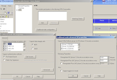 You configure encryption and integrity, specify to use a pre-shared secret (although you won't be able to enter one just yet) and in the "Advanced" options you can specify DH and lifetimes.
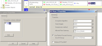 In this case we're using 3DES/MD5, DH group 2 and specifying which interoperable device the VPN is talking to.
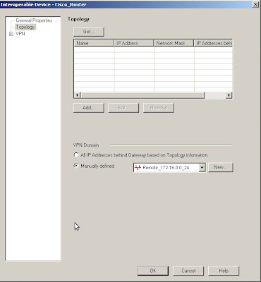 The encryption domains on Checkpoint are defined as properties of the gateway objects. Edit the interoperable device and open the "Toplogy" page, you can either manually set the topology or use another object to represent the encryption domain.
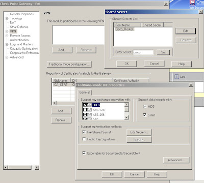 Edit your own Checkpoint enforcement module and open the VPN "Traditional mode configuration", then use the "Edit Secrets" button and you should see an entry for each of your VPN peers that have the "Pre-Shared Secret" box ticked.
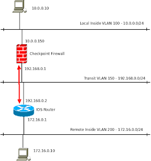
ip route 10.0.0.0 255.255.255.0 192.168.0.2In reality you may not need this as for internet-based site-to-site VPNs the routers default route often does the job.
crypto isakmp policy 10
encr aes 256
hash sha
authentication pre-share
group 2
crypto isakmp key cisco address 192.168.0.1
crypto ipsec transform-set TESTSET esp-aes 256 esp-sha-hmac
ip access-list extended VPN_INTERESTING_TRAFFIC
permit ip 172.16.0.0 0.0.0.255 10.0.0.0 0.0.0.255 log
 crypto map VPN_MAP 10 ipsec-isakmp
set peer 192.168.0.1
set transform-set TESTSET
set pfs group2
match address VPN_INTERESTING_TRAFFIC
Cisco_Router(config)#interface fastethernet 0/0
Cisco_Router(config-if)#crypto map VPN_MAP
*Mar  1 00:25:33.187: %CRYPTO-6-ISAKMP_ON_OFF: ISAKMP is ON